
Special electronic paper front light structure

A technology of electronic paper and optics, applied in optics, nonlinear optics, instruments, etc., can solve the problems of expensive mold opening, increasing the surface thickness of electronic paper display modules, and the size cannot be changed at will

Pending Publication Date: 2021-05-18
亚世光电(集团)股份有限公司
View PDF0 Cites 0 Cited by
  • Summary
  • Abstract
  • Description
  • Claims
  • Application Information

AI Technical Summary

Problems solved by technology

However, nowadays, the light guide plate is usually made of acrylic or PC board, and the manufacturing method is nano-imprinting. The display module is opaque, so the LED light bar can only be installed on the side of the light guide plate, which will cause uneven light emission. The place close to the LED light bar emits brighter than the place far away from the LED light bar; the thickness of the electronic paper display device itself is 1.0mm, the thickness of the light guide plate is generally 0.4mm, the light guide plate needs to be attached to the electronic paper display device through OCA glue, and the overall thickness will reach 1.9mm, which greatly increases the surface thickness of the electronic paper display module and affects the overall product. The installation had a serious impact on

Method used


Image

  • Special electronic paper front light structure
  • Special electronic paper front light structure
  • Special electronic paper front light structure

Examples


Embodiment Construction

[0028] The specific embodiments provided by the present invention will be described in detail below in conjunction with the accompanying drawings.

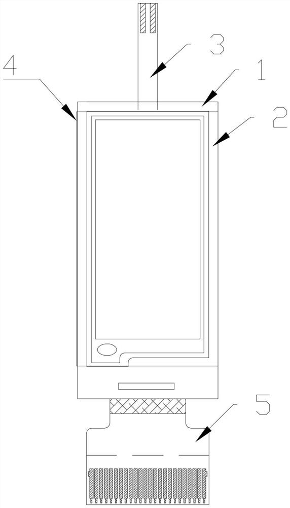
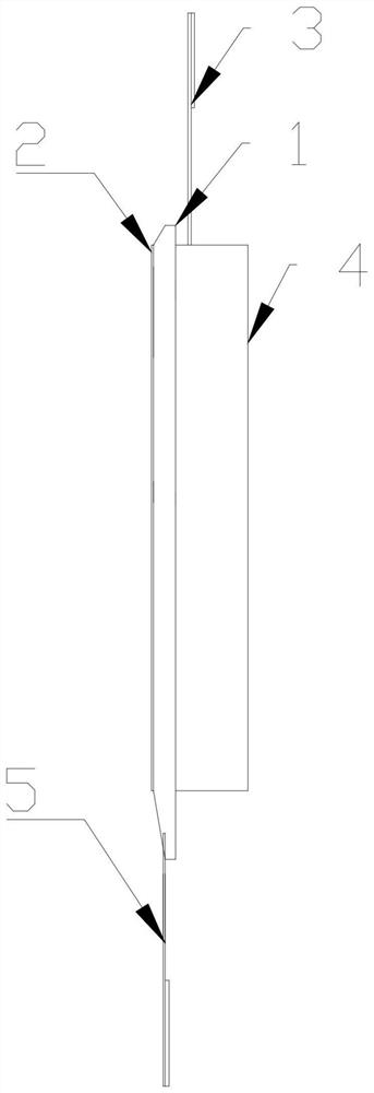
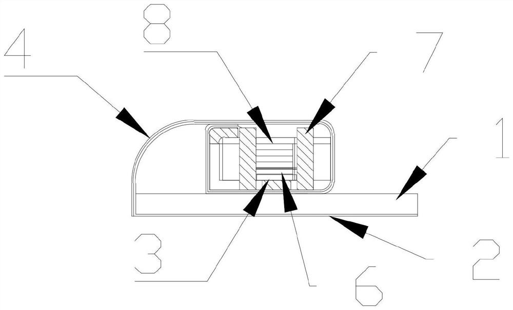
[0029] Such as Figure 1-13 As shown, an electronic paper front light structure includes a flexible optical light guide film (2), an electronic paper display module (1), a fixed iron frame (7), a toothed light guide plastic frame (8), and an LED lamp ( 6), LED light bar FPC (3), aluminum foil reflective film (4).

[0030] The front end of the flexible optical light guide film (2) is bonded to the display surface of the electronic paper display module (1) through OCA glue, the outside of the rear end is bonded to the aluminum foil reflective film (4), and the flexible optical light guide film (2) The rear end also wraps the fixed iron frame (7), the tooth-shaped light guide plastic frame (8) and the LED lamp (6) inside, and fixes it on the back of the electronic paper display module (1) after wrapping. The fixed iron frame (7) is...


PUM


Abstract

The invention provides an electronic paper front light structure. The electronic paper front light structure comprises a flexible optical light guide film, an electronic paper display module, a fixing iron frame, a tooth-shaped light guide plastic frame, an LED light strip and an aluminum foil reflecting film, wherein the front end of the flexible optical light guide film is attached to the display surface of the electronic paper display module through OCA glue, the exterior of the rear end of the flexible optical light guide film is attached to the aluminum foil reflecting film, the fixing iron frame, the tooth-shaped light guide plastic frame and the LED lamp strip are wrapped by the rear end of the flexible optical light guide film, and the components are fixed to the back of the electronic paper display module after being wrapped. The defects that the size and the appearance of the light guide plate cannot be changed at will and the mold opening cost is high are overcome, and the cost is effectively reduced; compared with a light guide plate, the flexible optical light guide film is good in light emitting effect, more uniform and softer in visual effect; and due to the light and thin characteristics of the flexible optical light guide film, the surface thickness of the electronic paper display module can be effectively reduced, and compared with the thicker thickness of a light guide plate, the surface transmittance of the electronic paper display module is effectively improved.

Description

technical field [0001] The invention relates to the technical field of liquid crystal displays, in particular to an electronic paper front light structure. Background technique [0002] In the current technology, the display principle of the electronic paper display module is the principle of electrophoresis, and the charged particles are driven by changing the electric field to generate a display image. Since the electronic paper display module itself does not have a light source and does not emit light to the outside world, users can only view the display content by relying on natural light or ambient light. Therefore, the electronic paper display module needs to be installed with a front light device, so that users It can also be used normally in a dark environment or an environment with weak external light. [0003] At present, the common front light device structure of the electronic paper display module is to attach a light guide plate on the top of the electronic pap...

Claims


Application Information

Patent Timeline
IPC IPC(8): G02F1/157
CPCG02F1/157
Inventor 牛红丽陈鑫
Owner 亚世光电(集团)股份有限公司
Learn More