Plugging device
A technology of blocking device and sealing part, which is applied in the fields of medical science, surgery, ligation, etc., can solve problems such as affecting the blocking performance and adversely affecting the stability of the left atrial appendage occluder.
- Summary
- Abstract
- Description
- Claims
- Application Information
AI Technical Summary
Problems solved by technology
Method used
Image

Examples
Embodiment approach 1
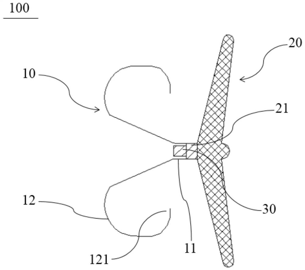
[0042] Such as figure 1 As shown, the occlusion device 100 of this embodiment includes a fixing part 10 and a sealing part 20 connected to the fixing part 10 . The sealing part 20 and the fixing part 10 are arranged at intervals along the axial direction of the occluding device 100 . The sealing part 20 is located at the proximal end of the occluding device 100 , and the fixing part 10 is located at the distal end of the occluding device 100 . The occlusion device 100 has a compressed state contained within the sheath for ease of delivery, and protrudes from the distal end of the sheath and self-expands and deploys as figure 1 The expanded state shown. The shape and figure 1 exactly the same or roughly the same. In other implementations, for example, when used for atrial septal defect occlusion, the sealing part 20 and the fixing part 10 can abut against each other after being released, and the middle part is connected by a connecting piece 30, so as to fix the occluding d...
Embodiment approach 2
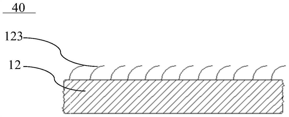
[0057] to combine figure 1 , image 3 and Figure 4 As shown, the overall structure of the occlusion device 100 of this embodiment is basically the same as that of the first embodiment, and also includes a fixed part 10 and a sealing part 20 connected to each other, and a drug supply part 40 is formed on the support rod 12 of the fixed part 10 . The difference from the first embodiment is that at least part of the surface of the support rod 12 in this embodiment is connected with a plurality of protrusions 123, and after the product is formed, the gap between two adjacent protrusions 123 is covered with at least For the drug 50 that promotes platelet aggregation, the protrusion 123 is covered with a first film in a compressed state, and the portion of the support rod 12 provided with the protrusion 123 constitutes the drug supply member 40 . Wherein, the function of the first thin film in this embodiment is the same as that in the first embodiment, and the material may be t...
Embodiment approach 3
[0061] In addition to using the drug supply part 40 as a part of the fixing part 10 in the first and second embodiments above, the drug supply part 40 may also be provided at other positions of the occlusion device 100 in the cavity of the left atrial appendage. to combine figure 1 and Figure 5 As shown, the overall structure of the occlusion device 100 of this embodiment is basically the same as that of Embodiment 1, the difference is that the drug supply part 40 of this embodiment is arranged between the fixing part 10 and the sealing part 20, and the drug supply part 40 includes The first housing 41, the first housing 41 is a hollow tubular structure with openings at both ends, the inside of the first housing 41 forms a drug storage cavity, and the drug storage cavity is provided with at least medicine for promoting platelet aggregation, the first shell The side wall of the body 41 is provided with a plurality of release holes 411 and at least one injection hole (not show...
PUM
 Abstract
Description
Claims
Application Information
 - R&D
- Intellectual Property
- Life Sciences
- Materials
- Tech Scout
- Unparalleled Data Quality
- Higher Quality Content
- 60% Fewer Hallucinations
Browse by: Latest US Patents, China's latest patents, Technical Efficacy Thesaurus, Application Domain, Technology Topic, Popular Technical Reports.
© 2025 PatSnap. All rights reserved.Legal|Privacy policy|Modern Slavery Act Transparency Statement|Sitemap|About US| Contact US: help@patsnap.com