

Pre-foaming machine for lost foam casting and working method thereof
A lost foam casting and pre-foaming technology, applied in casting and molding equipment and other directions, can solve the problems of multiple labor resources, complex processing process, consumption, etc., to achieve the effect of simple use and improved automation
- Summary
- Abstract
- Description
- Claims
- Application Information
AI Technical Summary
Problems solved by technology
Method used
Image

Examples
no. 1 example
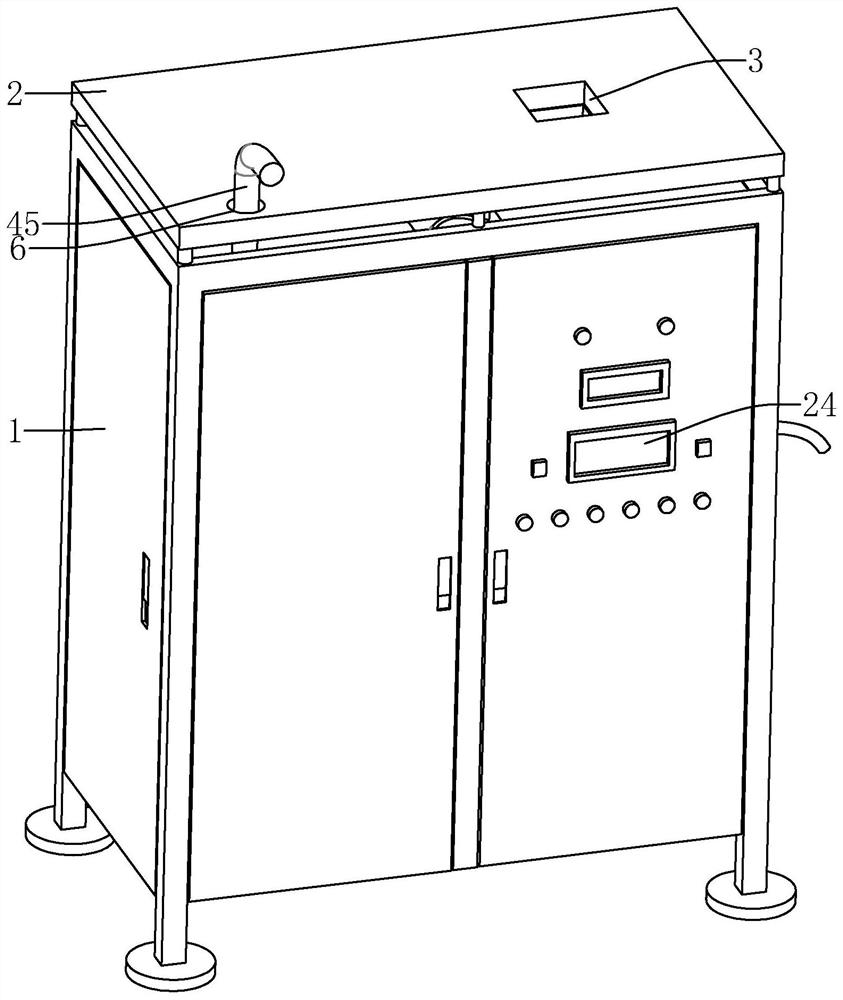
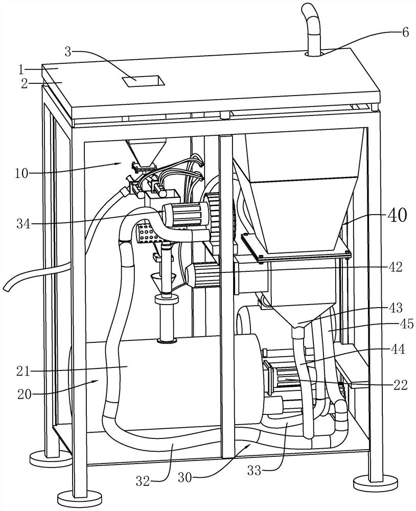
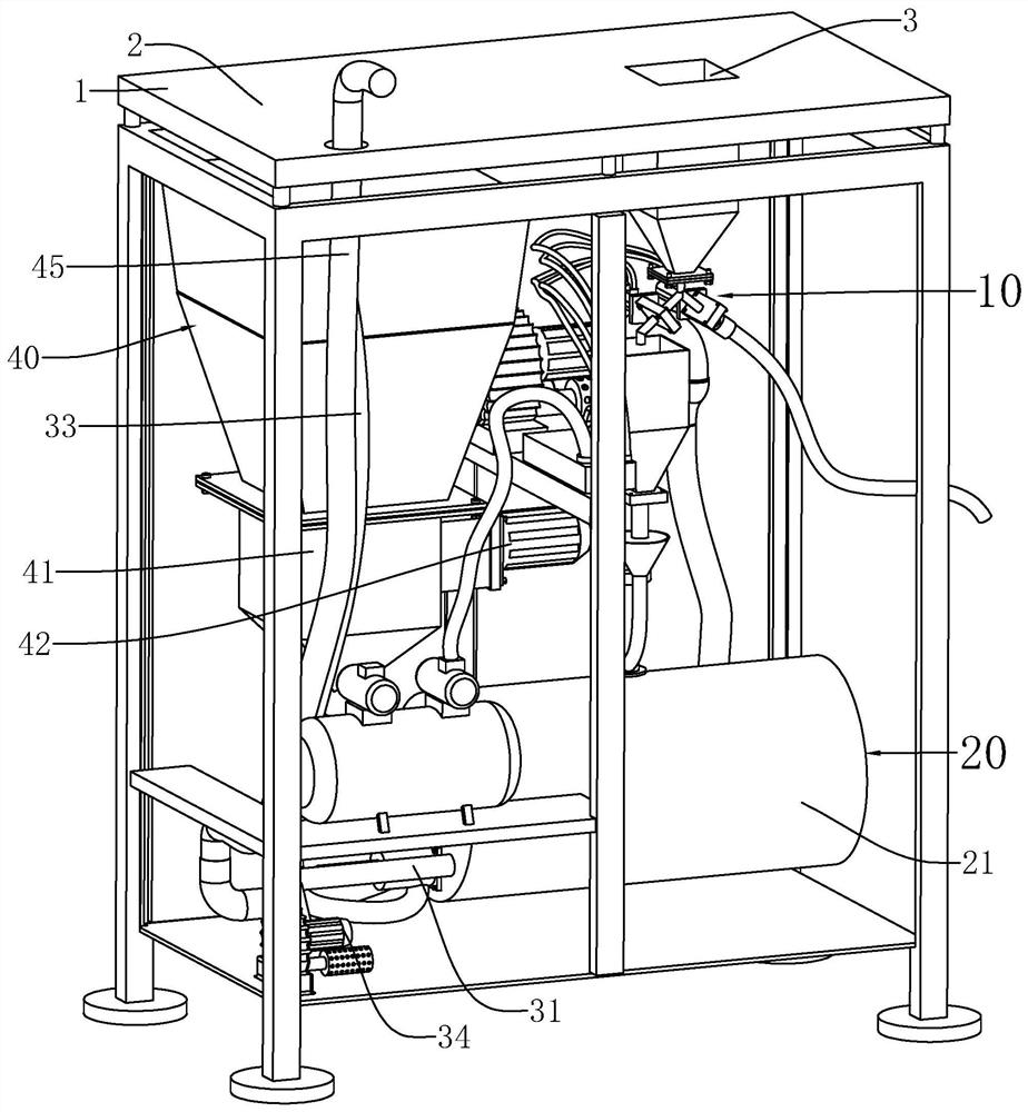
[0051] Such as Figure 1 to Figure 3 As shown, the present invention provides a pre-foaming machine for lost foam casting, which includes a casing 1 , a feeding assembly 10 , a heating assembly 20 , a conveying pipe 30 and a crushing assembly 40 .
[0052] The casing 1 has a top wall 2 , and the top wall 2 has a feeding port 3 and an outlet 6 ; the feeding assembly 10 is arranged inside the casing 1 and below the feeding port 3 . The heating assembly 20 is connected with the feeding assembly 10, and the heating assembly 20 includes a heating chamber 21 and a stirrer 22, and the stirring member 22 is arranged in the heating chamber 21; the conveying pipeline 30 has a first compressed air pipe 31, a second compressed air pipe 32 and an outlet The air pipe 33, the upstream ends of the first compressed air pipe 31 and the second compressed air pipe 32 are all connected to a compressed air pump 34, and the compressed air pump 34 may be two independent pumps. The downstream end of ...
no. 2 example
[0062] Such as Figure 8 and Figure 9 As shown, the transmission pipeline also includes a blowback assembly 50, and the blowback assembly 50 includes a communication pipe 54, and the communication pipe 54 has a first plug port 51, a second plug port 52 and a third plug port 53, the first plug port 51 and the third plug port 53 The first discharge pipe 44 is connected, the second socket 52 is connected with the second compressed air pipe 32, the third socket 53 is connected with the second discharge pipe 45, and the second compressed air pipe 32 is in the second socket 52 The insertion section 55 extends beyond the first socket 51 .
[0063] The working method of the pre-foaming machine that the lost foam casting of the present embodiment is used is as follows:
[0064] In S7: the crushed material enters the connecting pipe 54 from the position of the first socket 51 along the first discharge pipe 44, and at the same time, the second compressed air pipe 32 supplies air flow ...
no. 3 example
[0066] Such as Figure 4 and Figure 5 As shown, the feeding assembly 10 has a feeding barrel 9, a tee pipe 11, a buffer barrel 12, a receiving bucket 13 and a feeding pipe 14 connected in sequence, and the downstream end of the feeding pipe 14 is connected with the heating chamber 21; the tee pipe 11 Including the first branch pipe 15, the second branch pipe 16 and the third branch pipe 17, the first branch pipe 15 is connected with the barrel outlet 8 of the feeding barrel 9, the second branch pipe 16 is connected with the buffer barrel 12, and the third branch pipe 17 is connected with the return pipe 18 Connected, the end of the return pipe 18 extends to the outside of the casing 1 . The top wall 2 has an outlet 6, and the second discharge pipe 45 extends from the outlet 6 to the outside of the casing 1;
[0067] There is a first valve on the second branch pipe 16, a second valve on the third branch pipe 17, the first valve has a first cylinder 161 and a first flashboard...
PUM
 Abstract
Description
Claims
Application Information