Screw extrusion type spray head device of 3D printer

A 3D printer and screw extrusion technology, applied in the field of 3D printing, can solve the problems of wire breakage, friction and extrusion force increase, blockage, etc., to control printing speed, improve extrusion accuracy, and prevent material deposition. Effect

Pending Publication Date: 2021-05-25
CHANGSHA UNIVERSITY OF SCIENCE AND TECHNOLOGY
View PDF0 Cites 2 Cited by
  • Summary
  • Abstract
  • Description
  • Claims
  • Application Information

AI Technical Summary

Problems solved by technology

[0005] (1) The materials used for printing are generally low melting point filamentous materials (such as ABS plastic filaments), but this material cannot meet people's high requirements for workpiece materials
[0006] (2) During the printing process, the printing speed can only be controlled by controlling the wire feeding speed to match the moving speed of the print head. If the wire feeding speed is too slow, the wire will break
[0007] (3) During the printing process, if the printing is suspended in the middle, and when the printing continues, the ABS plastic wire may generate external force due to its thermal expansion, and the friction and extrusion force between the material tube and the wire material will increase, and the wire material will The upper and lower ends of the inner wall of the material tube move, causing blockage
[0011] (2) Extrusion from the nozzle of the printer usually cannot control the speed of the material extruded by the nozzle well
[0012] (3) It is impossible to prevent deposition problems caused by uneven density after mixing metal and ceramic printing materials with binders

Method used


Image

  • Screw extrusion type spray head device of 3D printer
  • Screw extrusion type spray head device of 3D printer
  • Screw extrusion type spray head device of 3D printer

Examples


Embodiment Construction

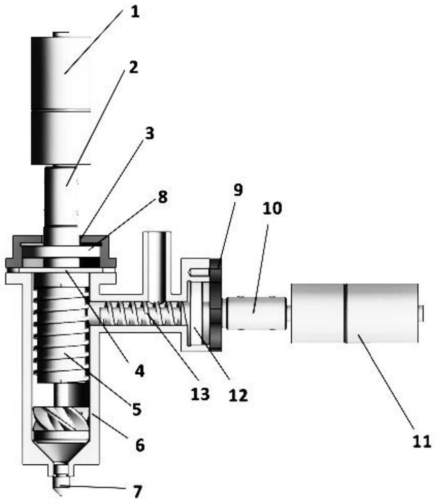
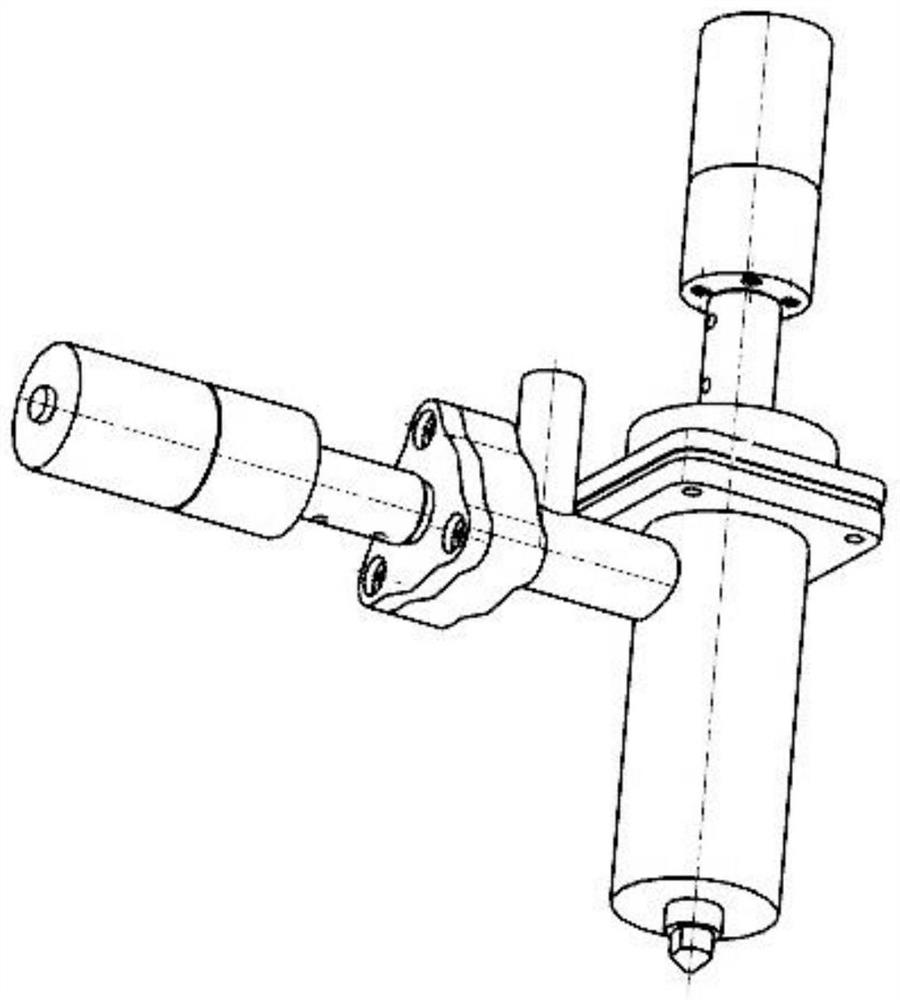
[0039] The technical solutions of the present invention will be clearly and completely described below in conjunction with the accompanying drawings.

[0040] In the description of the present invention, it should be noted that the terms "center", "upper", "lower", "left", "right", "vertical", "horizontal", "inner", "outer" etc. The indicated orientation or positional relationship is based on the orientation or positional relationship shown in the drawings, and is only for the convenience of describing the present invention and simplifying the description, rather than indicating or implying that the referred device or element must have a specific orientation, or in a specific orientation. construction and operation, and therefore cannot be construed as limiting the present invention; moreover, the terms "first", "second", and "third" are used for descriptive purposes only, and cannot be construed as indicating or implying relative importance.

[0041] In the description of the...


PUM

PropertyMeasurementUnit
Large diameteraaaaaaaaaa
Thread widthaaaaaaaaaa
Pitchaaaaaaaaaa

Abstract

The invention relates to a screw extrusion type spray head device of a 3D printer. The screw extrusion type spray head device of the 3D printer comprises a motor, an upper end cover, a charging barrel, a feeding end cover, a feeding port, an extrusion screw rod, a nozzle, a feeding screw rod, an elastic check ring for a hole and a bearing. The feeding screw rod and the extrusion screw rod are both driven by speed-adjustable motors to rotate, and the extrusion speed of the spray head can be controlled by controlling the rotating speeds of the motors. The lower end of the extrusion screw rod is provided with blades with the screw direction opposite to that of the screw rod, so that the deposition phenomenon caused by non-uniform density of a molten material is prevented, when the motor drives the extrusion screw rod to rotate, resistance force generated by the blades upwards stirs the molten material extruded down by the extrusion screw rod, and meanwhile, gaps are formed in the middle of the blades so that the material can flow downwards.

Description

technical field [0001] The present invention relates to the field of 3D printing technology, in particular to a 3D printer spiral extrusion nozzle device, especially a nozzle kit device for uniform printing of powder materials (such as metals, ceramics, etc.). Background technique [0002] At present, 3D printing is divided into direct printing and indirect printing. [0003] Direct printing is that the nozzle mechanism of the printer uses the heating jacket to directly heat the wire material sent to the material tube by the wire feeding mechanism. The material is heated and melted in the nozzle, and then it is filled layer by layer according to the cross-sectional profile and motion track derived from the model slice by the computer. Then solidify in the air, and after layer by layer, the physical object can be printed out; [0004] However, the printer heads of the existing direct-printed FDM 3D printers generally have the following defects. [0005] (1) The materials us...

Claims


Application Information

Patent Timeline
IPC IPC(8): B29C64/209B29C64/153B33Y30/00
CPCB33Y30/00B29C64/153B29C64/209
Inventor 仝永刚唐佳荟邓吨英张鹏柳建蔡志海王斌
Owner CHANGSHA UNIVERSITY OF SCIENCE AND TECHNOLOGY
Why Eureka
Try Eureka