Eureka AIR delivers breakthrough ideas for toughest innovation challenges, trusted by R&D personnel around the world.

Anechoic tile attached to outer surface of underwater vehicle shell and underwater vehicle

A technology for underwater vehicles and anechoic tiles, which is applied to underwater ships, underwater operating equipment, chemical instruments and methods, etc., can solve problems such as cavity deformation, large size, and poor sound absorption effect, and achieve excellent absorption Acoustic performance, optimized performance, effects of high structural strength

Pending Publication Date: 2021-05-25
CAIHONG DRONE TECH CO LTD
View PDF0 Cites 0 Cited by
  • Summary
  • Abstract
  • Description
  • Claims
  • Application Information

AI Technical Summary

Problems solved by technology

The impedance transition type often has a single structural material, the size is too large, and the sound absorption effect is poor; the cavity resonance type structure is prone to deformation of the internal cavity due to external pressure; the particle filling type often relies on other types of structural design, and the preparation process of the local resonance type structure complex, technically imperfect
[0003] At present, most studies on the structure of anechoic tiles tend to stay in the above medium and high frequency range, and do not consider the analysis of the influence of deep water pressure on the structure. During the preparation process, adhesives are added to fix each layer, which affects the sound absorption performance of the anechoic tile structure.

Method used


Image

  • Anechoic tile attached to outer surface of underwater vehicle shell and underwater vehicle
  • Anechoic tile attached to outer surface of underwater vehicle shell and underwater vehicle
  • Anechoic tile attached to outer surface of underwater vehicle shell and underwater vehicle

Examples


Embodiment Construction

[0033] The present invention will be described in more detail below. While the present invention has provided preferred embodiments, it should be understood that the invention can be embodied in various forms and should not be limited by the embodiments set forth herein. Rather, these embodiments are provided so that this disclosure will be thorough and complete, and will fully convey the scope of the invention to those skilled in the art.

[0034] In the description of the present invention, it should be noted that the terms "center", "upper", "lower", "left", "right", "vertical", "horizontal", "inner", "outer" etc. The indicated orientation or positional relationship is based on the orientation or positional relationship shown in the drawings, and is only for the convenience of describing the present invention and simplifying the description, rather than indicating or implying that the referred device or element must have a specific orientation, or in a specific orientation....


PUM

PropertyMeasurementUnit
Radiusaaaaaaaaaa
Thicknessaaaaaaaaaa
Thicknessaaaaaaaaaa

Abstract

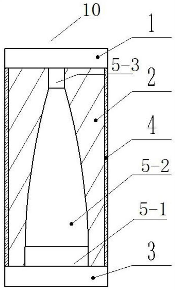
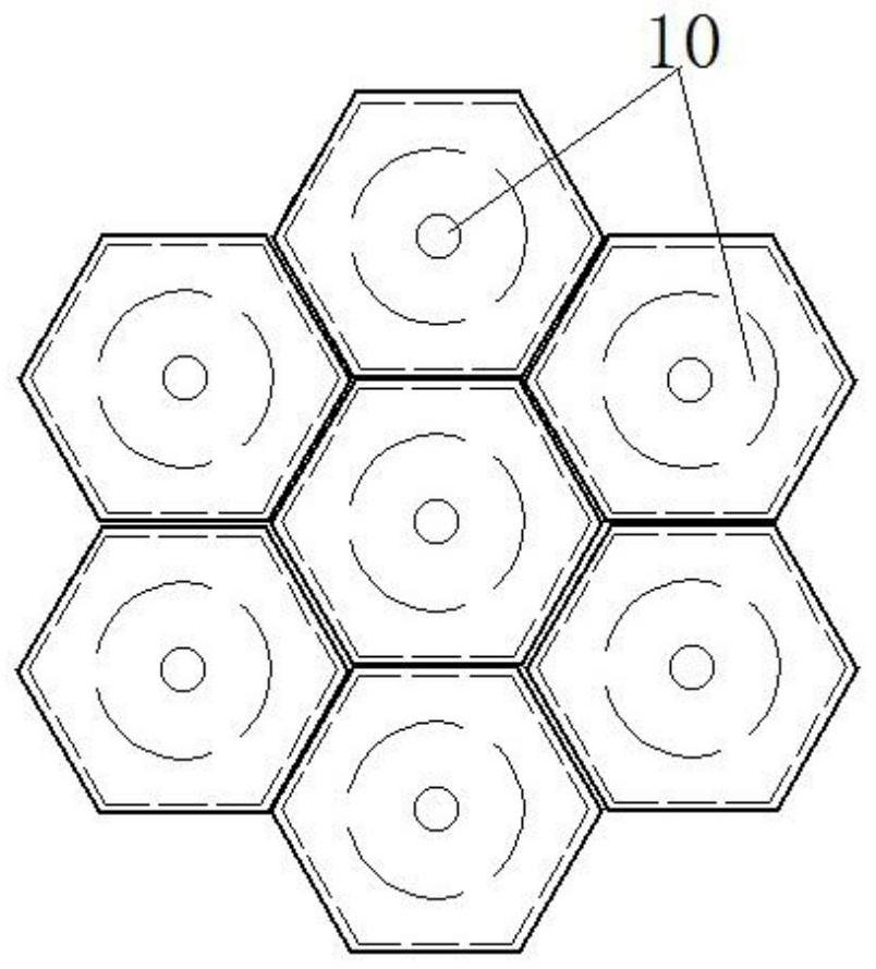
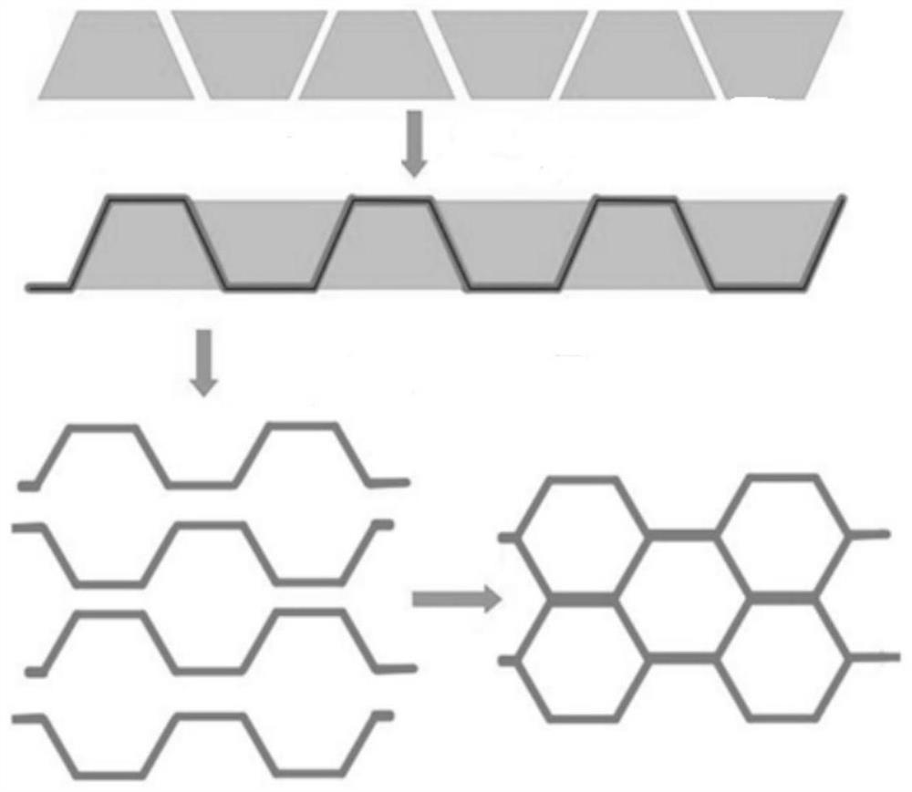
The invention discloses an anechoic tile attached to the outer surface of an underwater vehicle shell and an underwater vehicle. The anechoic tile is formed by closely arranging a plurality of regular hexagonal prism-shaped unit cell structures which are connected, wherein each unit cell structure sequentially comprises a base layer, a sound absorption layer and a sound transmission layer in the direction from the position close to the shell to the position away from the shell, and projections of a regular hexagon formed by the outer surface contours of the three parts in the axis direction of the regular hexagonal prism coincide; and the sound absorption layer comprises an internal material layer and a carbon fiber framework wrapping the internal material layer, the outer contours of the carbon fiber framework and the internal material layer are both regular hexagons, and a cavity longitudinally penetrating through the internal material layer is formed in the internal material layer. According to the anechoic tile structure, the carbon fiber honeycomb serves as an internal framework, and the problem that a cavity of a sound absorption structure deforms under deep water is solved. In addition, excellent sound absorption performance is achieved in low, medium and high frequency bands.

Description

technical field [0001] The invention belongs to the technical field of underwater sound absorption and noise reduction stealth, and in particular relates to a sound-absorbing tile attached to the outer surface of an underwater vehicle shell and the underwater vehicle. Background technique [0002] Submarines have become a very threatening naval vessel because of their invisibility. The underwater anechoic covering technology can not only reduce the target strength of submarines but also suppress its radiation noise. It can also be used to reduce self-noise in sonar platform areas. A comprehensive technology. The current anechoic tile structure mainly includes particle filling type, impedance transition type, cavity resonance type and relatively new local resonance type. The impedance transition type often has a single structural material, the size is too large, and the sound absorption effect is poor; the cavity resonance type structure is prone to deformation of the intern...

Claims


Application Information

Patent Timeline
IPC IPC(8): B32B3/26B32B3/12B32B27/38B32B27/40B32B27/08B32B25/14B32B25/08B32B7/12B32B27/18B32B9/00B32B9/04B32B27/06B32B33/00B63G8/34
CPCB32B3/26B32B5/02B32B3/12B32B5/18B32B27/38B32B27/40B32B27/08B32B25/14B32B25/08B32B7/12B32B27/18B32B33/00B63G8/34B32B2262/106B32B2266/0278B32B2307/10B32B2605/16
Inventor 王宗辉
Owner CAIHONG DRONE TECH CO LTD
Why Eureka
Eureka Blog
Learn More