Slope drainage structure and method

A drainage structure and slope technology, applied in the field of slope drainage structure, can solve problems such as easy blockage, high use cost, and long construction period of underground drainage tunnels, and achieve the effect of increased drainage flow and easy cleaning

Pending Publication Date: 2021-05-25
ZHEJIANG SCI RES INST OF TRANSPORT
View PDF0 Cites 5 Cited by
  • Summary
  • Abstract
  • Description
  • Claims
  • Application Information

AI Technical Summary

Problems solved by technology

Surface drainage measures such as surface drainage ditches and blind drainage ditches have limited drainage capacity and can only be used for slope drainage, and cannot discharge groundwater that infiltrates into the interior of the slope; water collection wells require power and regular management, which consumes a lot of energy and costs. High; due to the small inclination angle of the horizontal drainage hole, it is easy to be blocked during the natural drainage process, which affects the long-term effectiveness of the drainage channel; the construction period of the underground drainage hole is long, the process is complicated, and the cost is high
Therefore, there is still a lack of methods for absorbing and draining groundwater from slopes, and it is still a matter of urgency to explore new technologies for cost-effective slope drainage.

Method used


Image

  • Slope drainage structure and method
  • Slope drainage structure and method
  • Slope drainage structure and method

Examples


Embodiment 1

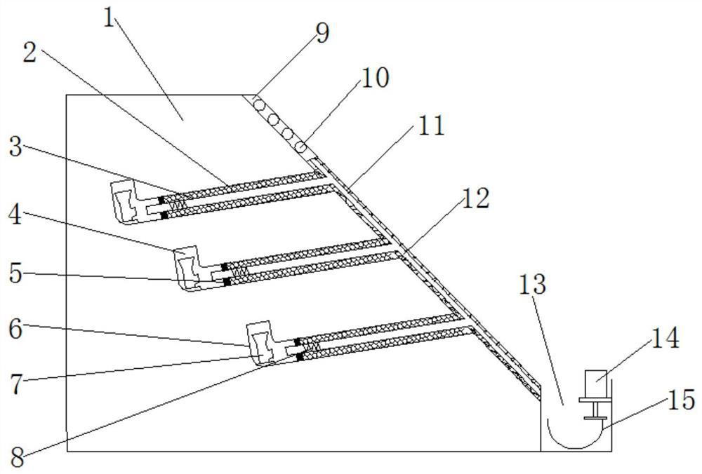
[0033]Example 1: When there is less water in the cavity of the permeable hole section 4, and the negative pressure in the cavity of the permeable hole section 4 can meet the initial condition of siphon, the accumulated water in the cavity of the permeable hole section 4 can be directly discharged through the drain pipe 12. The nozzle is naturally and actively discharged to the side ditch 13 under the action of siphon.

Embodiment 2

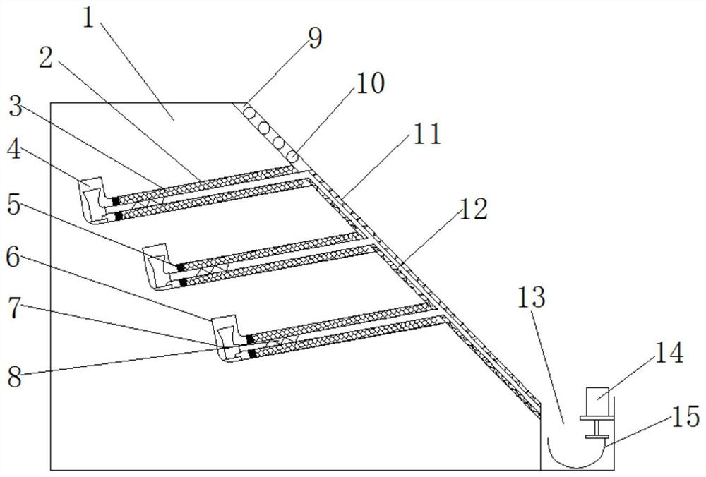
[0034] Embodiment 2: When the water content of the entire slope 1 is large, the water-absorbing swelling filler 3 fully absorbs water and expands, driving the telescopic hose section 8 to elongate, and the water inlet of the drain pipe 12 extends to the magnetic pipe 7 docking port 20, thereby passing through the magnetic pipe 7. The water inlet of the tube 7 is water, and the water inlet of the magnetic tube 7 is set in a trumpet shape to increase the water flow rate, increase the height difference between the cavity and the water outlet, and further accelerate the discharge of the water in the cavity. When the water in the cavity is reduced, the water will expand and fill The material 3 is gradually reduced, while the magnetic tube 7 and the magnetic block 5 repel each other with the same sex, and the dehydration reduction of the water-absorbing swelling filler 3 and the reduction of the flexible hose section 8 are accelerated under the action of magnetic force.

Embodiment 3

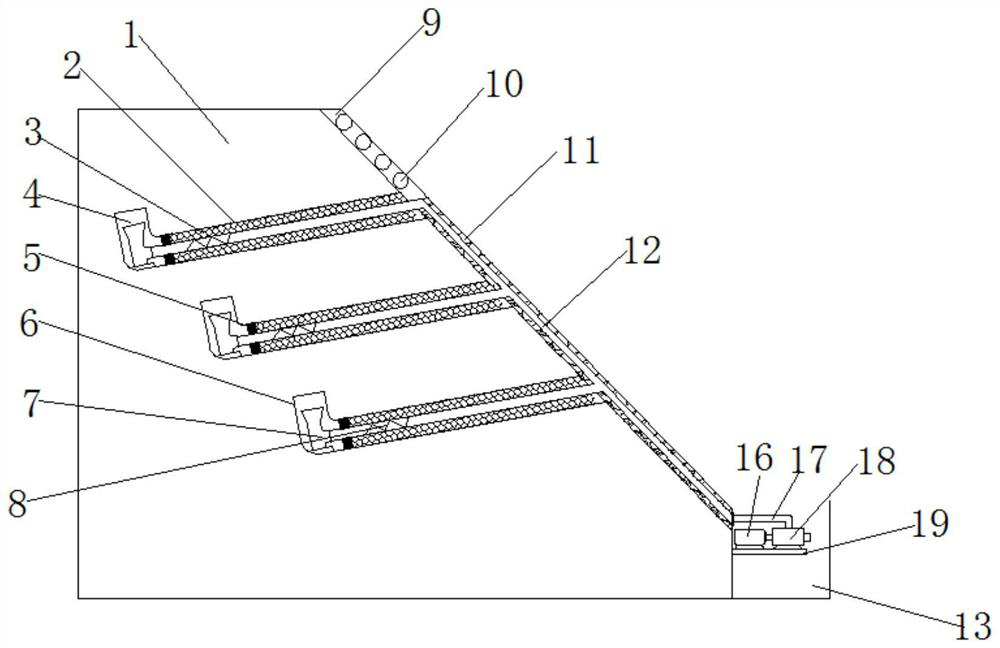
[0035] Embodiment 3: When encountering extreme weather such as continuous heavy rainfall emergency drainage, if the negative pressure of slope 1 permeable hole section 4 is insufficient to implement siphon active drainage, or a large number of air bubbles are generated in the drain pipe 12 to hinder siphon drainage, then the water pump The water inlet of 18 is connected to the water outlet of the drain pipe 12 through the water suction pipe 17, the motor 16 and the water pump 18 are turned on, and the passive pumping of the groundwater inside the slope 1 is realized through the water pump 18, and the water pump 12 can provide the initial negative pressure value of siphon drainage at the same time .


PUM


Abstract

The invention relates to a slope drainage structure and method. The slope drainage structure comprises a slope, drilled holes, drainage grooves and drainage pipes, wherein the drainage grooves are formed in the slope surface of the slope; a plurality of groups of drilled holes are distributed and formed inside the slope; each drilled hole is divided into a filling section and a water permeable hole section; each filling section is filled with water absorption expansion fillers; a magnetic pipe is fixedly arranged at the bottom end of each water permeable hole section; and drainage pipes are arranged in the drilled holes. The slope drainage structure adopts a double-water-drainage-pipe mode. When water in a cavity of the water permeable hole section is little, the water is directly drained through water inlet openings of water drainage pipelines. When the water content of the whole slope is great, the water absorption expansion fillers expand through absorbing water, telescopic soft pipe sections are driven to extend, the water inlet openings of the water drainage pipelines extend to a magnetic pipe butt joint opening to increase the pipe diameter of the drainage pipes and increase the height difference of water drainage openings and a water permeable cavity, and the drainage flow rate is increased; and after water quantity reduction through sufficient drainage, the water absorption expansion fillers are restored, the telescopic soft pipe sections are restored under the effect of magnetic force, and the water inlet openings are separated from the butt joint opening.

Description

technical field [0001] The invention relates to the technical field of road engineering, in particular to a slope drainage structure and method. Background technique [0002] Rainfall-type landslides are widely distributed in my country, including the Yunnan-Guizhou-Sichuan area, the loess area, and the southeast coastal areas, especially shallow soil landslides often occur in the southeast coastal areas of Zhejiang, Fujian, and Jiangxi. Taking Zhejiang Province as an example, because Zhejiang is greatly affected by typhoons every year, there is a lot of rainfall from July to September every year, the soil on the surface of the mountain is full of water, the weight of the soil increases, and the mechanical properties are greatly reduced. In addition, in recent years A large number of human engineering activities such as excavation of roads, railways, and civil buildings have finally led to frequent landslides. Generally speaking, the volume of this kind of landslide is not ...

Claims


Application Information

Patent Timeline
Patent Type & Authority Applications(China)
IPC IPC(8): E02D3/10E03F3/04E02D17/20B01D29/01B01D29/96A01G9/02
CPCA01G9/02B01D29/01B01D29/96E02D3/10E02D17/20E03F3/04E03F3/046
Inventor 詹伟余以强肖旦强胡智叶霄
Owner ZHEJIANG SCI RES INST OF TRANSPORT
Why Eureka
Try Eureka