Bearing arrangement

A bearing configuration and bearing technology, which is applied to bearings, bearing cooling, shafts and bearings, etc., can solve problems such as shortening service life and increasing thrust bearing load, and achieves the effect of high load capacity and high axial load capacity

Pending Publication Date: 2021-05-25
AB SKF
View PDF0 Cites 0 Cited by
  • Summary
  • Abstract
  • Description
  • Claims
  • Application Information

AI Technical Summary

Problems solved by technology

This increases the load on the thrust bearing and shortens the service life

Method used


Image

  • Bearing arrangement
  • Bearing arrangement
  • Bearing arrangement

Examples


Embodiment Construction

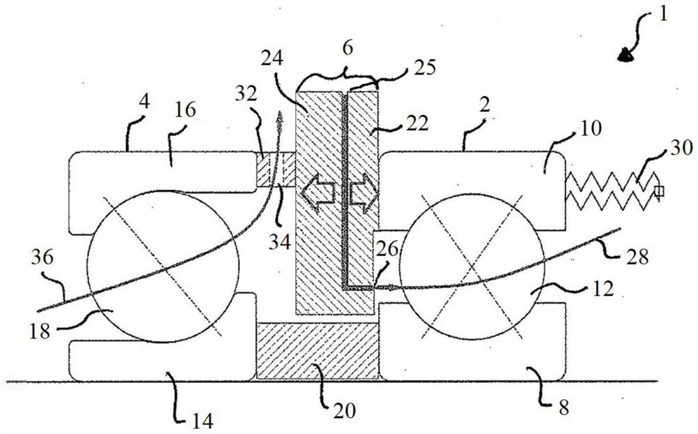
[0082] figure 1 A part of a bearing arrangement 1 is shown, which is shown with two bearings 2 , 4 . A balancing piston 6 is arranged between the two bearings 2 , 4 .

[0083] The bearing 2 is a four-point contact ball bearing with an inner ring 8, an outer ring 10 and rolling elements 12, the rolling elements 12 being balls. Bearing 2 can support axial loads in both directions, and can also support limited radial loads.

[0084] The bearing 4 is a thrust bearing with an inner ring 14, an outer ring 16 and rolling elements 18, which in this case are balls. In this embodiment, the bearing 4 is only subjected to axial loads. Bearing 2 and bearing 4 are separated by a spacer 20 at their inner rings 8 and 14 .

[0085] In order to reduce the forces on the bearing 4 , the bearing arrangement 1 comprises a compensating piston 6 . The balancing piston 6 comprises a first part 22 and a second part 24 . The first part 22 and the second part 24 contact the outer rings 10, 16 of th...


PUM


Abstract

Disclosed is a bearing arrangement. The bearing arrangement comprises at least two bearings and a balance piston; each bearing is provided with an inner ring and an outer ring; the inner rings of the at least two bearings are mounted on a shaft; the balance piston is arranged between the two bearings; the balance piston comprises a first part, a second part, an inlet, and an outlet; the first part and the second part are in contact with the outer rings of the two bearings in the axial direction; the inlet is used for guiding pressure fluid between the first part and the second part so as to provide pressure for the first part and the second part; the balancing piston is used for adjusting an axial force acting on at least one bearing of the two bearings; the outlet is used for guiding the pressure fluid as a lubricant to at least one of the two bearings; and / or the outer diameter of the balancing piston is larger than the outer diameters of the outer rings of the bearings.

Description

technical field [0001] The invention relates to a bearing arrangement according to the preamble of technical solution 1 . Background technique [0002] The axial load capacity of a rolling bearing depends on the bearing contact angle as well as the type, size and number of rolling elements. Bearings can also be arranged side by side to increase the total load capacity. The contact angle is defined as the contact angle inside the bearing. The larger the contact angle, the higher the axial load capacity. [0003] At high speeds, the centrifugal force on the rolling elements produces an induced axial force acting on the shaft in the opposite direction of the external force. The larger the contact angle, the larger the induced force. If the induced force is greater than the external force, it will cause axial displacement of the shaft in the opposite direction to that of the external force. This situation must be avoided. This can happen, for example, in screw compressors ...

Claims


Application Information

Patent Timeline
Patent Type & Authority Applications(China)
IPC IPC(8): F16C19/54F16C33/66F16C37/00
CPCF16C19/54F16C33/6659F16C37/007F16C25/08F16C19/166F16C19/541F16C19/546F16C33/6677F16C2360/43F16C19/542F16C19/547
Inventor 夏本奎汉斯·瓦林
Owner AB SKF
Why Eureka
Try Eureka