
High-pressure quick-opening ball valve

A ball valve, high pressure technology, applied in the valve details, valve device, valve shell structure and other directions, can solve the problem of ball valve switching torque and switching time increase, the ball valve is difficult to meet the fast switching, the scope of application is small, etc., to reduce the torque, meet the Quick opening requirements and strong applicability

Inactive Publication Date: 2021-05-25
LUOYANG THREE TURNS SPECIAL VALVES
View PDF7 Cites 0 Cited by
  • Summary
  • Abstract
  • Description
  • Claims
  • Application Information

AI Technical Summary

Problems solved by technology

As the caliber and pressure of the ball valve increase, the switching torque and switching time of the ball valve also increase accordingly, and the selected actuators increase accordingly. It is difficult for the existing ball valve to meet the requirements of fast switching.
[0003] In the gas explosion quick-opening valves in other industries, the medium is high-pressure gas, one end is connected to the high-pressure air source, and the other end is connected to the air. The high-pressure air source drives the piston to move quickly to achieve quick opening, but the pressure of the air source needs to be specially adjusted during use. , and the medium can only be high-pressure gas, the scope of application is small

Method used


Image

  • High-pressure quick-opening ball valve
  • High-pressure quick-opening ball valve
  • High-pressure quick-opening ball valve

Examples


Embodiment Construction

[0017] The technical solution of the present invention will be described in detail below through specific examples.

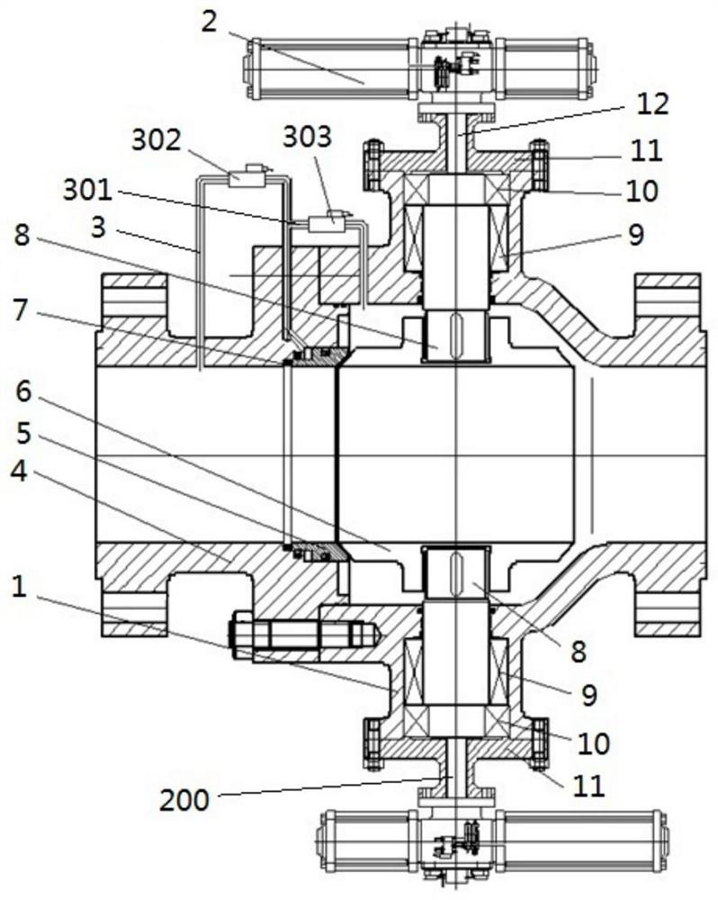
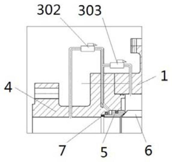
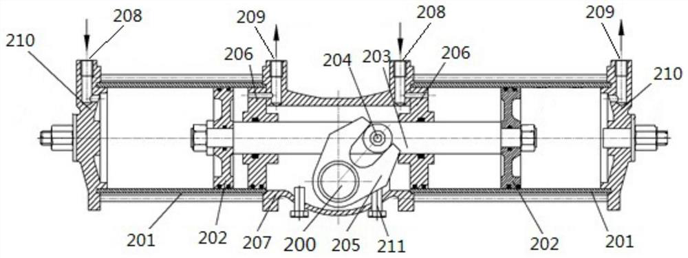
[0018] Such as Figure 1 to Figure 4 As shown, the high-pressure quick-opening ball valve includes a valve body 1, a valve cover 4 and an actuator 2. The valve body 1 includes a valve cavity and a ball 6 located in the valve cavity. The valve cover 4 is connected to the left side of the valve body 1 by bolts and nuts. The left side of the ball 6 is provided with a valve seat 5, and the valve cover 4 is provided with a medium inflow hole, and the outer peripheral surface of the valve seat 5 is tightly matched with the medium inflow hole of the valve cover 4. There is a medium outflow hole on the right side. The actuator 2 includes a rotating shaft 200. The ball 6 and the rotating shaft 200 are connected and rotated synchronously through the valve stem 8. An elastic member 7 is pressed between the valve seat 5 and the valve cover 4. The valve cover 4 A connectin...


PUM


Abstract

The invention provides a high-pressure quick-opening ball valve. The high-pressure quick-opening ball valve comprises a valve body, a valve cover and an executing mechanism, wherein a connecting pipeline communicated with a medium inflow hole is connected to the valve cover, a first hydraulic electromagnetic valve is arranged in the connecting pipeline, a pressure relief branch is connected to the connecting pipeline, and a second hydraulic electromagnetic valve is arranged in the pressure relief branch; the first hydraulic electromagnetic valve is located on the upstream of the pressure relief branch, an outlet of the connecting pipeline is located at the left side of a valve seat, an outlet of the pressure relief branch is located in a valve cavity at the right side of the valve seat, the executing mechanism comprises a cylinder body and a piston, a pin shaft is fixed to a piston rod, a shifting fork is fixed to a rotating shaft, and the pin shaft moves in a fork opening of the shifting fork in a guiding manner; and a first ventilation opening and a second ventilation opening which are communicated with a cylinder body are formed in the two sides of the piston respectively, and before the valve is opened, ventilation is conducted on the first ventilation opening of the executing mechanism, and when the valve is opened, the first hydraulic electromagnetic valve is closed, the second hydraulic electromagnetic valve is opened, a medium enters a valve cavity in the right side of the valve seat through the pressure relief branch, and the executing mechanism drives the ball valve to be rapidly opened.

Description

technical field [0001] The invention relates to the technical field of valves, in particular to a high-pressure quick-opening ball valve. Background technique [0002] At present, the general switching time of emergency shut-off valves used in the petrochemical industry is: 3s~5s for small-diameter valves, and 8s-10s for large-diameter valves. It is almost impossible to achieve rapid shutdown in milliseconds. As the caliber and pressure of the ball valve increase, the switching torque and switching time of the ball valve also increase accordingly, and the selected actuators increase accordingly. It is difficult for the existing ball valve to meet the requirements of fast switching. [0003] In the gas explosion quick-opening valves in other industries, the medium is high-pressure gas, one end is connected to the high-pressure air source, and the other end is connected to the air. The high-pressure air source drives the piston to move quickly to achieve quick opening, but the...

Claims


Application Information

Patent Timeline
IPC IPC(8): F16K5/06F16K5/08F16K5/20F16K27/06F16K31/122
CPCF16K5/0647F16K5/0694F16K5/0689F16K5/08F16K5/20F16K27/067F16K31/1225
Inventor 楚洛亿毕雪王志飞陈楠楠
Owner LUOYANG THREE TURNS SPECIAL VALVES
Learn More