
Positive-pressure airflow forced seed conveying and guiding pipe

A technology of seed guide tube and air flow, which is applied in the direction of sowing, sowing seeder, planter parts, etc., which can solve the problem of friction and collision between seeds and the inner wall of the seed guide tube, which will affect the operation efficiency, sowing qualification rate and consistent plant distance Improve the efficiency of planting operation and improve the quality of operation, etc., and achieve the effect of simple and convenient regulation, high efficiency of seeding operation, and novel structure

Pending Publication Date: 2021-05-28
NORTHEAST AGRICULTURAL UNIVERSITY
View PDF0 Cites 0 Cited by
  • Summary
  • Abstract
  • Description
  • Claims
  • Application Information

AI Technical Summary

Problems solved by technology

This structure has problems such as the collision and friction between the seeds and the pipe wall during the falling seeding process, resulting in low seed guiding speed and large bouncing of falling seeds, which cannot meet the current requirements of high-speed seeding and precision seeding operations, affecting operating efficiency and seeding qualification rate and distance consistency
In order to solve the above problems, a kind of seed metering device with airflow seed delivery has been studied. However, due to the deficiencies and defects in the design of the input structure of the seeds and the flow structure of the airflow, the friction and collision between the seeds and the inner wall of the seed introduction tube are not the same. The problem has not been eliminated, the problem has not been completely solved, and the efficiency and quality of sowing operations still need to be improved

Method used


Image

  • Positive-pressure airflow forced seed conveying and guiding pipe

Examples


Embodiment Construction

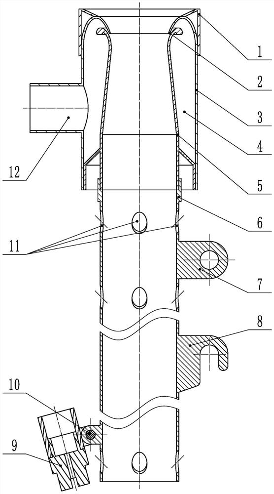
[0009]The present invention has been described in detail below with reference to the accompanying drawings. A positive pressure gas stream is forced to specify the catheter tube, and in the outer portion of the cylindrical inner casing 5, the outer side of the cylindrical inner casing 5 is provided with the inner side of the cylinder housing 3. The annular gas chamber 4 is provided with an annular airway 2 at a portion between the upper end of the cylindrical inner casing 5 and the upper end of the cylindrical casing 3, the annular gas chamber 4 through the annular valve 2 and a cylindrical inner casing 5 The inner cavity is connected, and the lower end of the annular gas chamber 4 is sealed; the pressure gas inlet 12 with the ring air chamber 4 is opened on the side wall of the cylinder outer casing 3, and the funnel-shaped inoculation cover 1 is fastened in the cylinder housing 3. On the upper end; the mounting tube 6 is sealed on the lower portion of the cylindrical inner casing ...


PUM


Abstract

A positive-pressure airflow forced seed conveying and guiding pipe belongs to agricultural machinery. A cylindrical outer shell sleeves a cylindrical inner shell, an annular air chamber is arranged between the cylindrical inner shell and the cylindrical outer shell, an annular air channel is arranged between the upper ends of the cylindrical inner shell and the cylindrical outer shell, the annular air chamber communicates with an inner cavity of the cylindrical inner shell through the annular air channel, a pressure air inlet communicating with the annular air chamber is formed in the side wall of the cylindrical outer shell, a funnel-shaped seed receiving cover is buckled on the upper end part of the cylindrical outer shell, a seed guiding pipe is hermetically mounted on the lower part of the cylindrical inner shell, a plurality of air inlets are formed in the side wall of the seed guiding pipe, and a water spray head is rotatably mounted on the outer wall surface of the bottom end of the seed guiding pipe through a dip angle adjusting and locking bolt group. The pipe eliminates collision and friction between seeds and the seed guiding pipe and bounce of the seeds on seedbed soil in the seed conveying process, and has the advantages of being unique, reasonable and simple in structure, high in seed conveying efficiency, good in seed conveying precision, reliable in use and easy and convenient to regulate and control.

Description

Technical field[0001]The present invention creates an agricultural machinery, mainly involving sowing work components.Background technique[0002]The catheter tube is a plastic mechanical working component, mainly used to broadcast the seeds in which the seeds after the crater is discharged, and in the soil. The existing guidelines are mostly non-auxiliary-free tubular structures, including two categories of hoses and hard tersons. When homogence, the seeds discharged from the cochoscope fall into the guidelines, and then rely on the seed self-gravity extending pipe hole, and the tube of the catheter falls into the species of the sowing machine opening. Inside the ditch. This structure has problems with collision, rubbing, friction, low-generating speed, etc. during the falling type of the seed, can't meet the current high-speed sowing and precision sowing operation requirements, affecting the efficiency and seeding rate And the line spacing consistency. In order to solve the above pr...

Claims


Application Information

Patent Timeline
Patent Type & Authority Applications(China)
IPC IPC(8): A01C7/20A01C7/08
CPCA01C7/206A01C7/081
Inventor 王奇王金武邓皓杰闫东伟唐汉周文琪
Owner NORTHEAST AGRICULTURAL UNIVERSITY
Features
  • Generate Ideas
  • Intellectual Property
  • Life Sciences
  • Materials
  • Tech Scout
  • Unparalleled Data Quality
  • Higher Quality Content
  • 60% Fewer Hallucinations
Learn More