Pulmonary ventilation function detection method, equipment and medium based on flow-volume loop diagram

A function testing and lung ventilation technology, applied in the field of medical testing, can solve the problems of unable to identify upper lung, unable to completely rule out cross infection, unable to identify left lung or right lung function decline, etc., to achieve suitable promotion and popularization, no cross infection, Experience relaxing effects

Active Publication Date: 2022-05-20
SHANGHAI JIAOTONG UNIV
View PDF8 Cites 0 Cited by
  • Summary
  • Abstract
  • Description
  • Claims
  • Application Information

AI Technical Summary

Problems solved by technology

However, the existing spirometer has certain limitations in detecting lung function. On the one hand, it can only detect changes in lung function but cannot identify whether the function of the left lung or the right lung has declined, let alone identify whether the function of the upper lung or the lower lung has decreased; On the one hand, in practical applications, the lung function instrument needs to exhale and inhale through the detection tube during the detection process. Although there are filters, the possibility of cross-infection cannot be completely ruled out.

Method used


Image

  • Pulmonary ventilation function detection method, equipment and medium based on flow-volume loop diagram
  • Pulmonary ventilation function detection method, equipment and medium based on flow-volume loop diagram
  • Pulmonary ventilation function detection method, equipment and medium based on flow-volume loop diagram

Examples


Embodiment 1

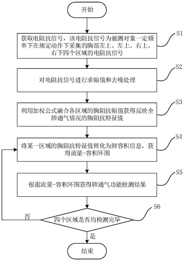
[0040] refer to figure 1 As shown, the present embodiment provides a method for detecting pulmonary ventilation function based on a flow-volume loop diagram, including:

[0041] Step S1, obtaining the electrical impedance signal of the object to be measured, the electrical impedance signal includes four areas of the upper left (LU area), upper right (RU area), lower left (LL area) and lower right (RL area) of the chest collected at a certain frequency The electrical impedance signal Z LU (n), Z RU (n), Z LL (n) and Z RL (n), where n is the serial number of the sampling sample.

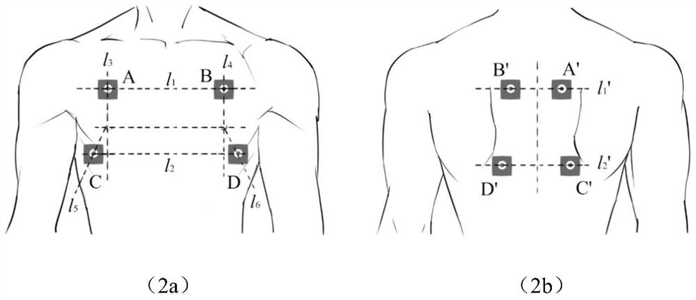
[0042] The electrical impedance signal is obtained through the measurement and collection of the bioelectrical impedance measurement system including four pairs of composite electrodes attached to the specified position on the surface of the chest cavity when the subject to be tested breathes according to the breathing action required by the flow-velocity loop diagram test of the clinical spiromete...

Embodiment 2

[0068] This embodiment provides an electronic device, including one or more processors, memory, and one or more programs stored in the memory, and the one or more programs include the method for performing chest impedance measurement as in Embodiment 1. Instructions of the method for detecting pulmonary ventilation function based on the flow-volume loop diagram.


PUM


Abstract

The invention relates to a method, device and medium for detecting pulmonary ventilation function based on a flow-volume loop diagram. The detection method includes the following steps: acquiring an electrical impedance signal of an object to be measured; and performing amplitude processing on the electrical impedance signal , obtain the thoracic impedance amplitude signal sequence reflecting the ventilation status of the four regions; fuse the thoracic impedance amplitude signal sequence of the four regions to obtain the thoracic impedance characteristic value sequence; transform the thoracic impedance characteristic value sequence into a lung Volume series, and perform digital differential processing on the lung volume series to obtain the lung ventilation flow series, generate the total flow-volume loop diagram and the flow-volume loop diagram of each area; obtain the total flow-volume loop diagram based on the flow-volume loop diagram Pulmonary ventilation function and test results of pulmonary ventilation function in each area. Compared with the prior art, the present invention has the advantages of simple and easy implementation of the measurement process, no risk of cross-infection, accuracy and reliability, popularization and application, and the like.

Description

technical field [0001] The invention relates to a medical detection method, in particular to a method, equipment and medium for detecting pulmonary ventilation function based on a flow-volume loop diagram. Background technique [0002] Chronic Obstructive Pulmonary Disease (COPD) is a common chronic respiratory disease and has become a global public health problem. Currently, lung function tests using spirometry are the gold standard for the diagnosis of COPD, which has important guiding significance for early detection of lung and airway lesions, assessment of disease severity and prognosis. In pulmonary function tests, the diagnostic criteria for COPD is that after inhalation of bronchodilators, if the one-second rate, that is, forced expiratory volume in the first second (FEV1) / forced vital capacity (FVC), is less than 70%, and FEV1 accounts for A percentage of predicted <80% indicates airflow limitation. However, the existing spirometer has certain limitations in de...

Claims


Application Information

Patent Timeline
Patent Type & Authority Patents(China)
IPC IPC(8): A61B5/08A61B5/085A61B5/053A61B5/087A61B5/091
CPCA61B5/0809A61B5/0816A61B5/085A61B5/087A61B5/091A61B5/0536A61B5/72
Inventor 马艺馨葛浩刘恩康张明珠白子轩
Owner SHANGHAI JIAOTONG UNIV
Why Eureka
Try Eureka