
Sludge treatment device

A sludge treatment and treatment room technology, applied in grain treatment, metal processing, manufacturing tools, etc., can solve the problem of affecting the crushing effect of equipment, crushing efficiency, easy bonding on the surface of mechanical crushing bodies, and poor crushing efficiency. and other problems, to achieve high cutting efficiency, ensure the segmentation effect, and achieve good results

Active Publication Date: 2021-05-28
三生环境科技股份有限公司
View PDF6 Cites 0 Cited by
  • Summary
  • Abstract
  • Description
  • Claims
  • Application Information

AI Technical Summary

Problems solved by technology

However, the sludge bonding block is relatively large, so the interior is mostly wet sludge, which is easily bonded to the surface of the mechanical crushing body during the crushing process, causing equipment blockage and affecting the crushing effect and efficiency of the equipment.
[0004] In view of the related technologies mentioned above, the inventor believes that the ordinary mechanical crushing method has the defects of poor crushing effect and crushing efficiency

Method used


Image

  • Sludge treatment device
  • Sludge treatment device
  • Sludge treatment device

Examples


Embodiment Construction

[0038] The following is attached Figure 1-6 The application is described in further detail.

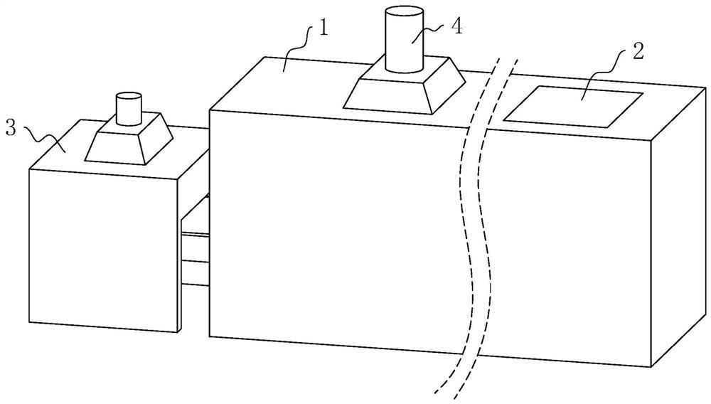
[0039] The embodiment of the present application discloses a sludge treatment device. refer to figure 1 , The sludge treatment device includes a treatment chamber 1, the upper end of the treatment chamber 1 is provided with a material inlet 2, one end of the treatment chamber 1 is provided with a drying box 3, and both the treatment chamber 1 and the drying box 3 are provided with a waste gas collection pipe 4. The sludge can be treated in the treatment chamber 1 and the drying box 3 , and the waste gas generated during the treatment process is discharged through the waste gas collection pipe 4 .

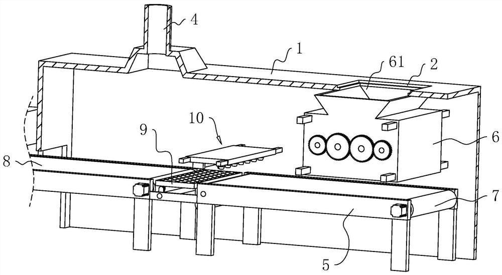
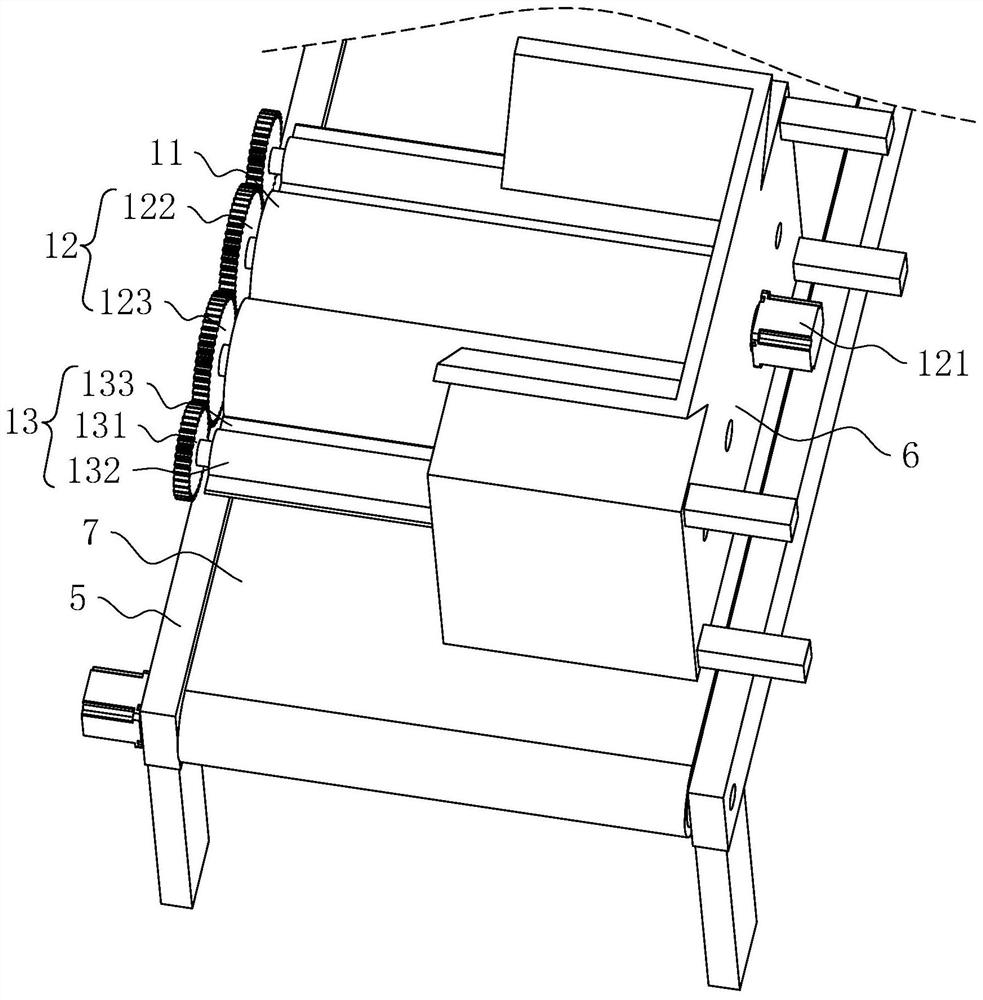
[0040] refer to figure 2, the processing chamber 1 is fixedly connected with a frame 5, and the processing chamber 1 is also fixedly connected with a pre-press box 6, the upper end of the pre-press box 6 is provided with a feed port 61, and the material inlet 2 is set corresponding to ...


PUM


Abstract

The invention relates to the field of sludge treatment, in particular to a sludge treatment device which comprises a treatment chamber, and a pre-pressing box is fixedly connected into the treatment chamber. A pre-pressing device is arranged in the pre-pressing box body, and the pre-pressing device comprises two grinding rollers rotationally connected with the pre-pressing box body. A first conveying belt is arranged on a machine frame, a cutting device is arranged above the first conveying belt, and a gap is reserved between the cutting device and the first conveying belt. When sludge is recycled, the sludge can enter the pre-pressing box body from a feeding opening, and the pre-pressing device in the pre-pressing box body enables large sludge to be rolled to be in a thin state. The sludge falls onto the first conveying belt, and the first conveying belt conveys the sludge. The cutting device can play a role in cutting the sludge, and as the gap is reserved between the cutting device and the first conveying belt, the sludge cannot adhere to the cutting device when the sludge is cut, so that the cutting effect and the cutting efficiency are ensured.

Description

technical field [0001] The present application relates to the field of sludge treatment, in particular to a sludge treatment device. Background technique [0002] Sludge treatment is a process of reducing, stabilizing and harmless sludge such as concentration, conditioning, dehydration, stabilization, drying or incineration. The higher the degree of wastewater treatment, the more sludge residues are generated that need to be disposed of. For modern sewage treatment plants, the treatment and disposal of sludge has become the most complex and expensive part of the operation of the sewage treatment system. [0003] Sludge is usually bonded together after recycling, so it generally needs to be pulverized before utilization, and the general treatment method is mechanical extrusion and crushing to make it into small pieces or small particles. However, the sludge sticking block is relatively large, so the interior is mostly wet sludge, which is easily bonded to the surface of the...

Claims


Application Information

Patent Timeline
IPC IPC(8): B02C4/02B02C4/42B02C4/28B02C4/40B02C23/20B26F3/00B30B3/04
CPCB02C4/02B02C4/42B02C4/286B02C4/40B02C23/20B26F3/004B30B3/04B02C2201/06
Inventor 王鑫海
Owner 三生环境科技股份有限公司
Learn More