Automatic and efficient cut-off waste rail device

A rail and automatic technology, applied in the direction of shearing devices, shearing machine accessories, metal processing equipment, etc., can solve the problems of limited service life of rails, high risk factor, high labor cost, etc.

Active Publication Date: 2022-03-18
广州砺风新材料科技有限公司
View PDF10 Cites 0 Cited by
  • Summary
  • Abstract
  • Description
  • Claims
  • Application Information

AI Technical Summary

Problems solved by technology

[0003] The service life of steel rails is limited, and waste rails need to be recycled and reused. The waste rails need to be cut off. Most of the existing cut-off methods are directly cut off by manual cutting machines. This cut-off method is inefficient and requires a lot of labor. Manpower to complete the treatment of scrap rails, the labor cost is relatively high, and the risk factor is high
The traditional way of truncating scrap rails can no longer meet the existing production needs

Method used


Image

  • Automatic and efficient cut-off waste rail device
  • Automatic and efficient cut-off waste rail device
  • Automatic and efficient cut-off waste rail device

Examples


Embodiment 1

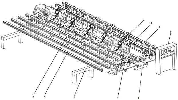
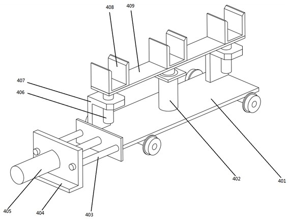
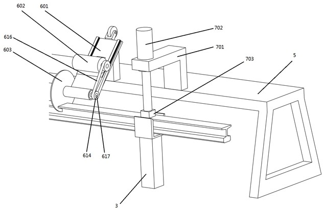
[0027] Example 1, such as figure 1 As shown in —7, the device for automatically and efficiently cutting waste rails includes a rail placement frame 1, the rail placement frame 1 is used to place waste rails 2, the right side of the rail placement frame 1 is provided with a fixed frame 5, and the right side of the rail placement frame 1 is provided with a Multiple rows of evenly arranged bracket mechanisms 3 for supporting the rail 2, the bracket mechanism 3 is used to place the rail 2, the structure of the bracket mechanism 3 is not limited, and the placement of the rail 2 can be realized without rotation That is, two symmetrically distributed moving mechanisms 4 for laterally moving the rail 2 are respectively provided on both sides of the bracket mechanism. , supporting plate 409, moving bracket 408, transverse guide rod 403, longitudinal guide rod 406, L-shaped guide plate 407, the transverse electric cylinder 405 is fixed on the fixed plate 404, and the output end of the t...


PUM


Abstract

The invention particularly relates to a device for automatically and efficiently cutting waste rails, which includes a rail placement frame, a fixed frame is provided on the right side of the rail placement frame, and multiple rows of evenly arranged support mechanisms are provided on the right side of the rail placement frame. There are two symmetrically distributed moving mechanisms on each side. Multiple cutting mechanisms and pressing mechanisms for cutting rails are fixed on the fixed frame. Idler mechanisms are evenly distributed between the rightmost row of bracket mechanisms. The front side of the roller mechanism is provided with a crushing mechanism; the present invention adopts the form of cutting first and then extruding to realize the cutting of the waste rail, adopts the moving mechanism to realize the lateral movement of the waste rail, and is equipped with a pressing mechanism to realize the rail’s cutting. Fixed, the automatic cutting of the rail can be realized by using the cutting machine that can move up and down, the longitudinal movement of the rail can be realized through the idler mechanism, and the crushing mechanism can be set to realize the compression and crushing of the cut rail.

Description

technical field [0001] The invention belongs to the technical field of waste steel rail processing, and in particular relates to a device for automatically and efficiently cutting waste steel rails. Background technique [0002] Steel rails are the main components of railway tracks. Its function is to guide the wheels of the rolling stock to move forward, bear the huge pressure of the wheels, and transmit them to the sleepers. The rails must provide the wheels with a continuous, smooth and least drag rolling surface. In the electrified railway or automatic blocking section, the rail can also be used as a track circuit. [0003] The service life of steel rails is limited, and waste rails need to be recycled and reused. The waste rails need to be cut off. Most of the existing cut-off methods are directly cut off by manual cutting machines. This cut-off method is inefficient and requires a lot of labor. Manpower to complete the treatment of scrap rails, the labor cost is rel...

Claims


Application Information

Patent Timeline
Patent Type & Authority Patents(China)
IPC IPC(8): B23D19/06B23D33/00B23D33/02
CPCB23D19/06B23D33/00B23D33/02
Inventor 牛文龙麻金凤孔晓宁
Owner 广州砺风新材料科技有限公司
Why Eureka
Try Eureka