Steel bar binding jig frame for component prefabrication

A technology of steel bar binding and tire frame, which is applied in the field of steel bar binding tire frame, can solve the problems of difficulty in ensuring the quality of rectangular steel bar frames, large labor waste, slow construction efficiency, etc., and achieves improved placement efficiency, high placement efficiency and accuracy. high effect

Active Publication Date: 2021-05-28
中铁二十三局集团第四工程有限公司 +1
View PDF12 Cites 5 Cited by
  • Summary
  • Abstract
  • Description
  • Claims
  • Application Information

AI Technical Summary

Problems solved by technology

[0005] The purpose of the present invention is to: in view of the prior art, the construction personnel place the steel bars on site based on the construction experience and bind them to prefabricate the rectangular steel frame. The construction efficiency is slow, the labor waste is large, and the quality of the bound rectangular steel frame is difficult to guarantee. problem, providing a steel bar binding tire frame for component prefabrication

Method used


Image

  • Steel bar binding jig frame for component prefabrication
  • Steel bar binding jig frame for component prefabrication
  • Steel bar binding jig frame for component prefabrication

Examples


Embodiment 1

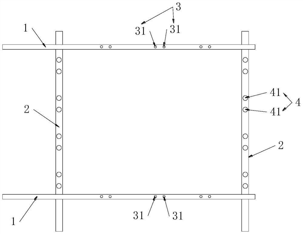
[0050] The present invention provides a steel bar binding tire frame for component prefabrication, see figure 1 , comprising two transverse supports 1 and two longitudinal supports 2, each of the transverse supports 1 is vertically connected to the two longitudinal supports 2;

[0051] The transverse support 1 is provided with a number of first positioning pieces 3, all of the first positioning pieces 3 are located between the two longitudinal supports 2, and are used for positioning the transverse reinforcement 12 relative to the two first positioning pieces 3 end of

[0052] The longitudinal support 2 is provided with a number of second positioning members 4, the second positioning members 4 are located between the two lateral supports 1, and are used for positioning the longitudinal reinforcing bars 22 relative to the two second positioning members 4. Ends.

[0053] The two transverse supports 1 are vertically connected with the two longitudinal supports 2 to form a recta...

Embodiment 2

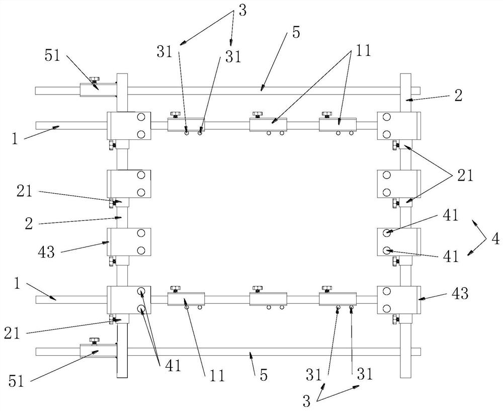
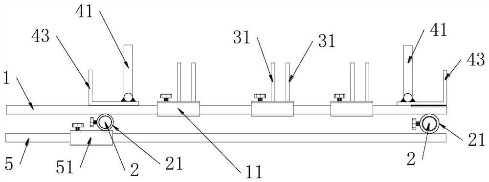
[0057] This embodiment provides a kind of steel bar binding frame for component prefabrication, see Figure 2-6 , which is different from the steel bar binding frame for component prefabrication described in the embodiment in that the first positioning part 3 is slidably connected to the corresponding lateral support 1, and the second locating part 4 is slidably connected to the corresponding The longitudinal support 2.

[0058] The first positioning member 3 can slide on the corresponding transverse support 1, and then adjust its position on the corresponding transverse support 1. According to the distance between two adjacent transverse steel bars 12 of the rectangular steel bar skeleton, Slidingly adjust the positions of the two adjacent first positioning members 3 accordingly, so that the same steel bar binding frame for component prefabrication can be applied to a rectangular steel bar frame with two adjacent transverse steel bars 12 with different spacings. The second p...


PUM


Abstract

The invention provides a steel bar binding jig frame for component prefabrication. The steel bar binding jig frame for component prefabrication comprises two transverse supports and two longitudinal supports, wherein a plurality of first positioning pieces are arranged on the transverse supports; and a plurality of second positioning pieces are arranged on the longitudinal supports. The transverse supports, the longitudinal supports, the first positioning pieces and the second positioning pieces are correspondingly arranged according to the position relation of transverse steel bars and longitudinal steel bars of the a rectangular steel bar framework, so that the two corresponding first positioning pieces can position the two ends of the transverse steel bars, the two corresponding second positioning pieces can position the two ends of the longitudinal steel bars, the positioning is more accurate, and the steel bar binding process is more stable. Before the transverse steel bars and the longitudinal steel bars are bound, the transverse steel bars and the longitudinal steel bars are placed through the steel bar binding jig frame for component prefabrication and then bound, so that the placing efficiency is high, the accuracy is high, the binding efficiency of the rectangular steel bar framework is effectively improved, the quality of the rectangular steel bar framework can be improved, and engineering construction is facilitated.

Description

technical field [0001] The invention relates to the technical field of reinforced concrete prefabricated components processing, in particular to a steel bar binding tire frame for component prefabrication. Background technique [0002] In the tunnel and slope protection construction of expressways and railways, due to the high standards and strict requirements of expressway and railway projects, the quality and progress requirements in the construction process of tunnels and slope protection are very high. In the process of tunnel construction, the central drainage ditch, the cable trench cover plate, and the slope protection hollow hexagonal blocks, curbstones, and frame edge stones in the subgrade engineering all have rectangular steel skeletons. The rectangular steel skeletons are generally A one-story or two-story structure, each including several transverse reinforcements and several longitudinal reinforcements; the longitudinal reinforcement can be a single reinforceme...

Claims


Application Information

Patent Timeline
Patent Type & Authority Applications(China)
IPC IPC(8): B28B23/02
CPCB28B23/024Y02A30/60
Inventor 刘长林杨俊东盛怀猛曾勇霖王晓明马艺虎张玉山王云鹏朱毓芳汤明月
Owner 中铁二十三局集团第四工程有限公司
Why Eureka
Try Eureka