Color master batch production system based on water cooling circulation and production method thereof

A production system and water cooling cycle technology, applied in the processing field of color masterbatch forming devices, can solve the problems of increasing the area occupied by the equipment, increasing the cost, increasing the number of equipment, etc., and achieving the effect of rapid heat transfer

Inactive Publication Date: 2021-05-28
李欢
View PDF3 Cites 1 Cited by
  • Summary
  • Abstract
  • Description
  • Claims
  • Application Information

AI Technical Summary

Problems solved by technology

[0003] When the color masterbatch is injection molded, the extruded linear and continuous masterbatch line is placed in the water tank to ensure that the water flow is still and avoid the deformation of the linear formed product caused by the fluctuation of the water, so that the masterbatch can be formed quickly. Generally, the length of the water storage tank is long, in order to conduct heat conduction more effectively, this will undoubtedly increase the area occupied by the equipment, and on this basis, the linear masterbatch is placed outside, and the extruded masterbatch is easy to stick to dust, and its quality It will become worse, and the cooling effect is poor. After molding, the masterbatch is cut into pellets, and the cut masterbatch is dried in a vacuum dryer, which increases the number of equipment for the complete set of products, which not only affects the processing efficiency, but also caused the problem of cost increase

Method used


Image

  • Color master batch production system based on water cooling circulation and production method thereof
  • Color master batch production system based on water cooling circulation and production method thereof
  • Color master batch production system based on water cooling circulation and production method thereof

Examples


Embodiment Construction

[0029] The implementation of the present application will be described in detail below with reference to the accompanying drawings and examples, so as to fully understand and implement the implementation process of how the present application uses technical means to solve technical problems and achieve technical effects.

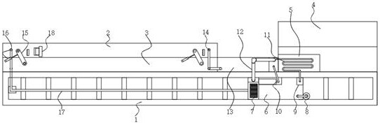
[0030] Such as Figure 1-8 As shown, the present invention provides a kind of color masterbatch production system based on water cooling cycle, comprising:

[0031] The base 1, the left side of the top of the base 1 is fixedly connected with the first sealing box 3, the front and rear sides of the first sealing box 3 are hinged with the second sealing box 2 through two hinged push rods 15, and the front and rear sides of the first sealing box 3 are close to One side of the articulated mandrel 15 is movably connected with one end of the articulated mandrel 15 through a hydraulic telescopic cylinder 16, the front and rear sides of the second sealed box 2 are p...


PUM


Abstract

The invention relates to the technical field of color master batch forming device processing, in particular to a color master batch production system based on water cooling circulation and a production method thereof. The color master batch production system comprises a base, a first sealing box is fixedly connected to the left side of the top of the base, second sealing boxes are hinged to the front side and the rear side of the first sealing box through two hinge ejector rods, and the sides, close to the hinge ejector rods, of the front side and the rear side of the first sealing box are movably connected with one ends of the hinge ejector rods through hydraulic telescopic air cylinders. By means of the design, it can be guaranteed that the temperature in the forming process is in a low state; due to full contact heat dissipation in a flowing water mode, linear color master batch forming can be more thorough and more uniform; through the built-in design, dust adhesion in the discharging process is avoided, and the master batch quality is improved; and as pelletizing is conducted in the cooling process, without existing independent drying treatment is not needed, the master batch does not need to be in contact with water for cooling in the whole operation process, the occupied area of equipment is effectively reduced, the purchase cost of the equipment is reduced, and the efficiency is higher.

Description

technical field [0001] The invention relates to the technical field of color masterbatch molding device processing, in particular to a color masterbatch production system and a production method based on water cooling cycle. Background technique [0002] Masterbatch refers to a plastic colorant that is well dispersed with a high proportion of pigments or additives and thermoplastic resins. The selected resin has good wetting and dispersing effects on the colorant, and has good compatibility with the material to be colored. compatibility. That is: pigment + carrier + additive = masterbatch. Masterbatch coloring is the most commonly used plastic coloring method today. [0003] When the color masterbatch is injection molded, the extruded linear and continuous masterbatch line is placed in the water tank to ensure that the water flow is still and avoid the deformation of the linear formed product caused by the fluctuation of the water, so that the masterbatch can be formed qui...

Claims


Application Information

Patent Timeline
Patent Type & Authority Applications(China)
IPC IPC(8): B29B9/02B29B13/04
CPCB29B9/02B29B13/04
Inventor 李欢
Owner 李欢
Why Eureka
Try Eureka