Manufacturing and forming process of environment-friendly paperboard packaging box
A molding process and packaging box technology, applied in the field of environmental protection cardboard packaging box production and molding process, can solve the problems of increasing equipment area, increasing production cost, reducing production efficiency, etc. The effect of a small footprint
- Summary
- Abstract
- Description
- Claims
- Application Information
AI Technical Summary
Problems solved by technology
Method used
Image


Examples
Embodiment Construction
[0028] The embodiments of the present invention will be described in detail below with reference to the accompanying drawings, but the present invention can be implemented in many different ways defined and covered by the claims.
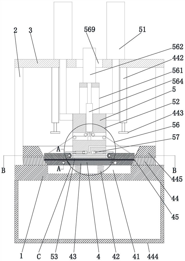
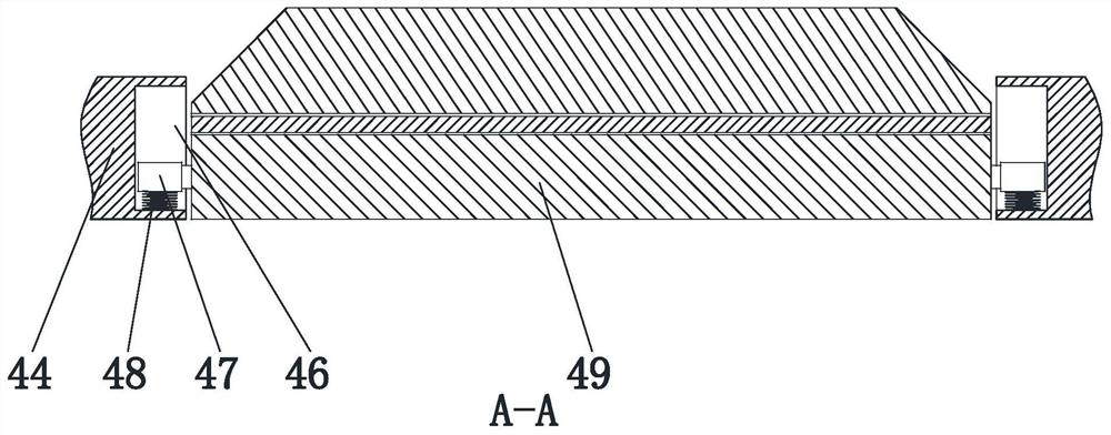
[0029] Such as Figure 1 to Figure 6 As shown, a molding process of an environmentally friendly cardboard packaging box, the molding process of the environmentally friendly cardboard packaging box adopts the following manufacturing molding equipment, the manufacturing molding equipment of the environmentally friendly cardboard packaging box includes a bottom plate 1, a fixed column 2, a top plate 3, and a supporting mechanism 4 and a compression forming mechanism 5, fixed columns 2 are installed at the four corners of the upper end surface of the bottom plate 1, the upper ends of the fixed columns 2 are respectively connected to the four corners of the lower end surface of the top plate 3, and the supporting mechanism 4 is arranged on the bottom plat...
PUM
 Abstract
Description
Claims
Application Information