Concrete pavement joint cutter

A technology for concrete pavement and slitting machine, which is applied in the field of slitting machine and concrete pavement slitting machine, can solve the problems of increasing the resistance of blade rotation and aggravating blade wear, and achieves the advantages of intensifying wear, prolonging length and maintaining sealing. Effect

Inactive Publication Date: 2021-05-28
刘盛
View PDF0 Cites 0 Cited by
  • Summary
  • Abstract
  • Description
  • Claims
  • Application Information

AI Technical Summary

Problems solved by technology

[0005] The technical problem to be solved by the present invention is to provide a concrete pavement slitting machine, one of the purposes of which is to have the ability to blow off the gravel attached to the surface of the blade when cutting, and to solve the problem of friction between the blade and the cement pavement when the pavement is cut. A large amount of dust will be generated, and the gravel in the dus

Method used


Image

  • Concrete pavement joint cutter
  • Concrete pavement joint cutter
  • Concrete pavement joint cutter

Examples


Embodiment 1

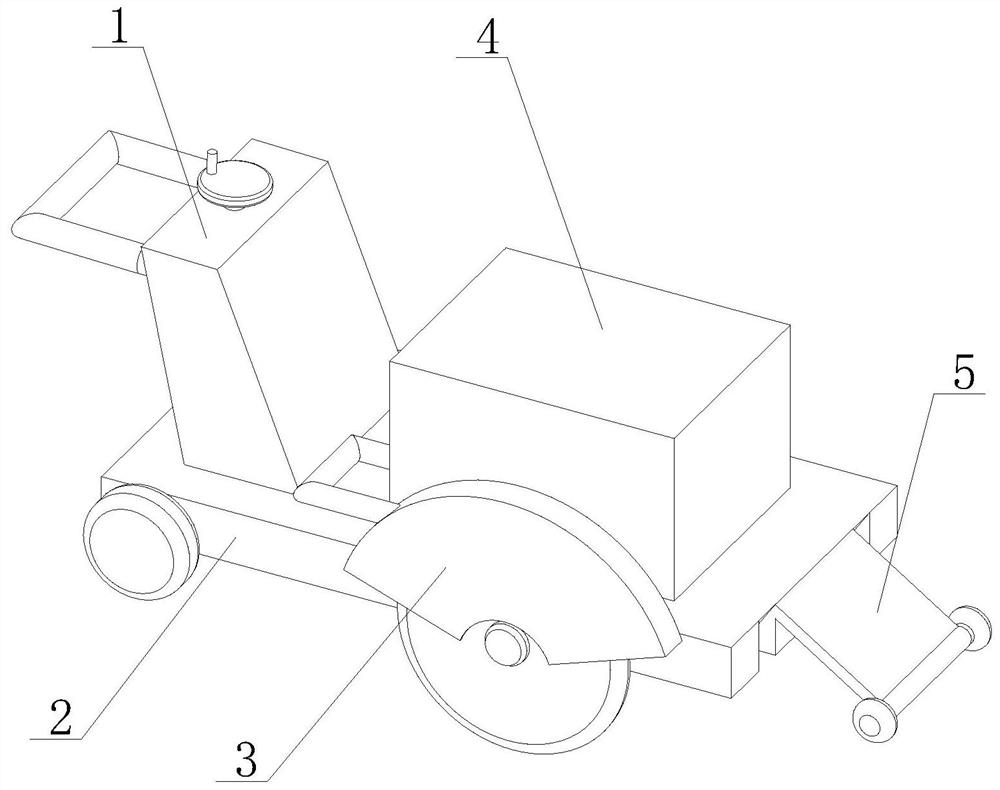
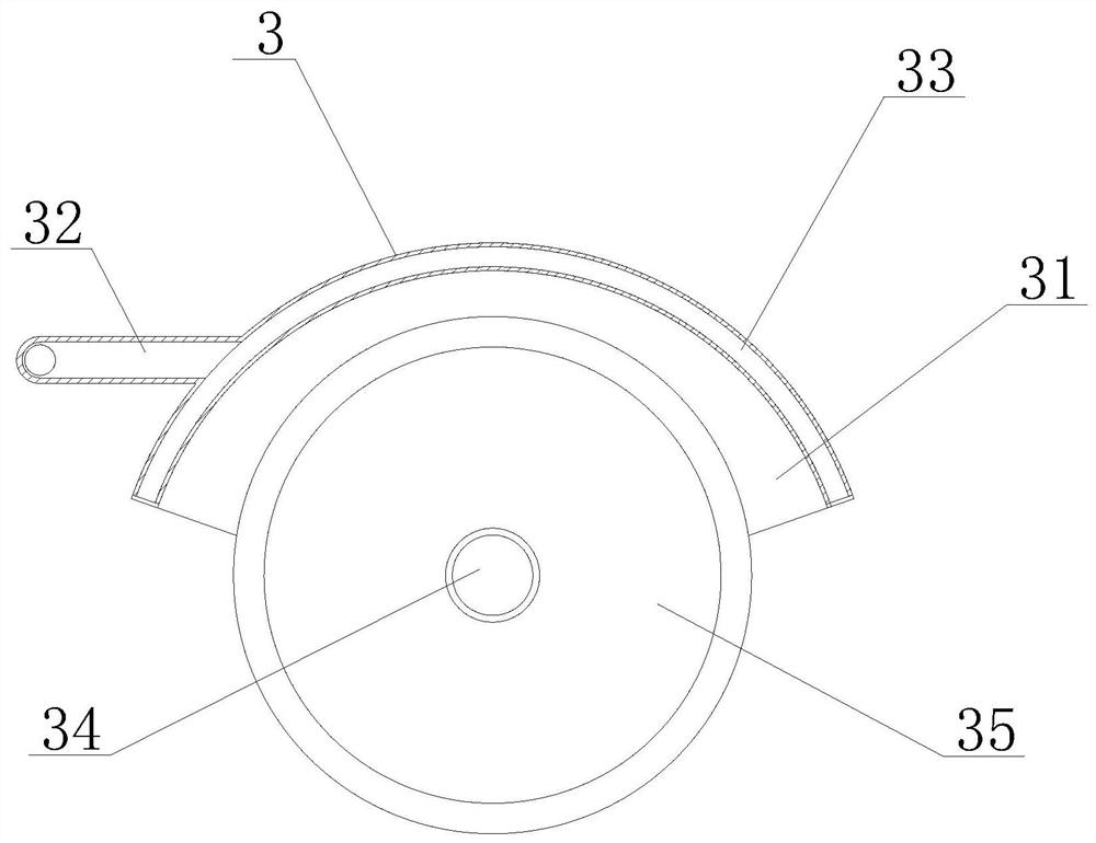
[0029] Such as Figure 1-Figure 6 As shown, the invention provides a concrete pavement cutting machine, comprising a control mechanism 1, the bottom surface of the control mechanism 1 is fixedly connected with a base mechanism 2, one side of the control mechanism 1 is provided with a power mechanism 4, and the bottom surface of the power mechanism 4 is connected to the The top of the base mechanism 2 is fixedly connected, the side of the base mechanism 2 away from the control mechanism 1 is fixedly installed with a guide wheel mechanism 5, the front of the power mechanism 4 is provided with a cutting mechanism 3, and the cutting mechanism 3 is fixedly installed on the outer wall of the base mechanism 2. The transmission connection between the mechanism 3 and the power mechanism 4, the cutting mechanism 3 includes a protective device 31, the top of the protective device 31 is provided with a water channel 33, one side of the protective device 31 is fixedly connected with a commu...

Embodiment 2

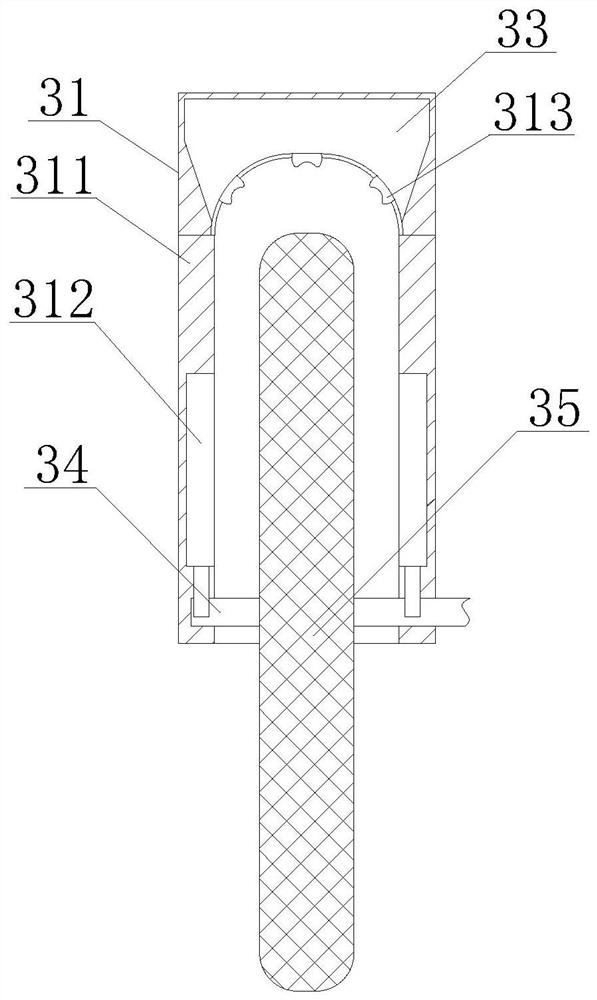
[0031] Such as Figure 6-8As shown, on the basis of Embodiment 1, the present invention provides a technical solution: the interior of the water inlet 1313 is provided with a communication device 131, the outer wall of the communication device 131 is fixedly connected with the inner wall of the water inlet 1313, and the lower part of the communication device 131 is provided There is a water storage cavity 132, and the interior of the water storage cavity 132 is provided with a fixed block 133, the outer wall of the fixed block 133 is fixedly connected with the inner wall of the water inlet 1313, and a movable plate 134 is arranged under the water storage cavity 132, and the two ends of the movable plate 134 are fixed Connected with the contact block 135, by adopting the combination of the fixed block 133, the movable plate 134, and the contact block 135, it can be realized that when the cutting piece 35 rotates at a high speed, a high-speed airflow will pass under the water inl...


PUM


Abstract

The invention discloses a concrete pavement joint cutter, and relates to the technical field of road construction, the concrete pavement joint cutter comprises a control mechanism, the bottom surface of the control mechanism is fixedly connected with a base mechanism, one side of the control mechanism is provided with a power mechanism, and the bottom surface of the power mechanism is fixedly connected with the top of the base mechanism; a guide wheel mechanism is fixedly installed on the side, away from the control mechanism, of the base mechanism, and a cutting mechanism is arranged on the front face of the power mechanism. Through combination of the rotating shaft and the air outlet device, a contact plate is conveniently pushed to move upwards to enable a pressing plate device to move in a compression cavity through impact force generated when the cutting blade makes contact with a road surface during cutting of the cutting blade, and therefore air in the compression cavity is discharged outwards through air outlet holes; dust and gravels on the surface of the cutting blade fall off along with airflow blown out of the air outlets, the gravels in the dust are prevented from being attached to the surface of the blade, the rotation resistance of the blade in the road surface can be increased when the blade cuts, and abrasion of the blade is aggravated.

Description

technical field [0001] The invention relates to a seam cutting machine, relates to the technical field of road construction, in particular to a seam cutting machine for concrete pavement. Background technique [0002] When the concrete pavement is being built, a slitting machine is usually used to slit the pavement, so that the pavement has expansion and contraction space when it expands under high temperature, and will not cause the pavement to burst, so that the pavement has a longer service life. There are following problems at prior art: [0003] 1. In the prior art, when the seam cutting machine is cutting the road surface, the friction between the blade and the cement road surface will generate a large amount of dust, and the gravel in the dust will adhere to the surface of the blade, which will increase the rotation of the blade in the road surface when cutting. Resistance, exacerbating the problem of blade wear; [0004] 2. In the prior art, for some cutting machin...

Claims


Application Information

Patent Timeline
IPC IPC(8): E01C23/09B08B3/02B08B5/02
CPCB08B3/022B08B5/023E01C23/0933
Inventor 刘盛
Owner 刘盛
Why Eureka
Try Eureka