High-reliability current frequency conversion circuit

A current-frequency conversion and reliability technology, applied in the direction of converting sensor output, measuring devices, instruments, etc., can solve problems such as loss of charge, inability to effectively guarantee the linearity of current-frequency conversion, poor working stability, etc.

Pending Publication Date: 2021-05-28
北京同芯科技有限公司
View PDF1 Cites 0 Cited by
  • Summary
  • Abstract
  • Description
  • Claims
  • Application Information

AI Technical Summary

Problems solved by technology

Therefore, there will be the following problems during work: 1), if there is a period during which the first switched capacitor and the second switched capacitor are connected at the same time during switching, the newly inserted empty capacitor will allocate the capacitor that should be removed. 2) If there is a period when the first switching capacitor and the second switching capacitor are not connected at the same time during switching, the circuit must have a constant integrated capacitor C0 to Store the charge that should be integrated during this period, otherwise the op amp will enter the open-loop working state and generate an exception, and lose the charge that should be integrated during this period
[0006] In summary, the current-frequency conversion circuit disclosed by the publication number CN106289333A has a complex structure and poor working stability when performing current-frequency conversion, and cannot effectively guarantee the linearity of the current-frequency conversion

Method used


Image

  • High-reliability current frequency conversion circuit
  • High-reliability current frequency conversion circuit
  • High-reliability current frequency conversion circuit

Examples


Embodiment Construction

[0039] The present invention will be further described below in conjunction with specific drawings and embodiments.

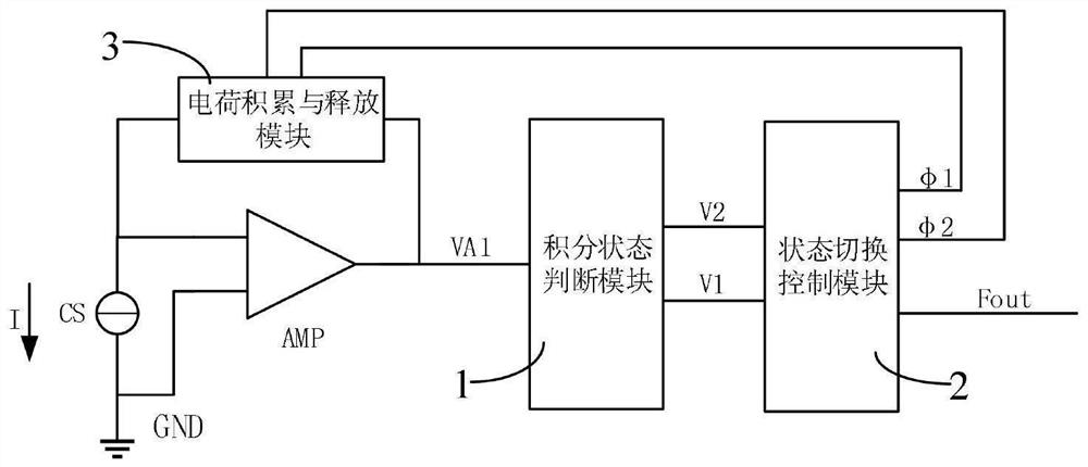
[0040] like figure 1 As shown: in order to eliminate the charge loss in the process of capacitor switching and ensure the linearity of current frequency conversion, the present invention includes an operational amplifier AMP adapted to the current source CS to be converted, and the output terminal of the current source CS is connected to the first terminal of the operational amplifier AMP terminal connection;

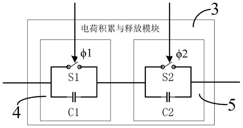
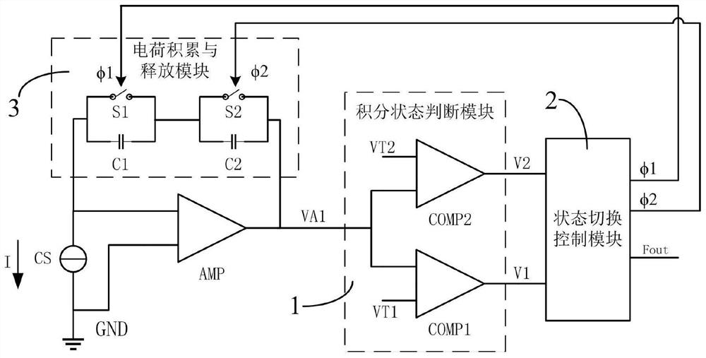
[0041] It also includes a charge accumulation and release module 3 adapted to be connected to the first end of the operational amplifier AMP and the output end of the operational amplifier AMP, an integral state judgment module 1 connected to the output end of the operational amplifier AMP, and an integrated state judgment module 1 connected to the output end of the operational amplifier AMP. The output terminal of module 1 is connected to the state swi...


PUM


Abstract

The invention relates to a high-reliability current frequency conversion circuit. The high-reliability current frequency conversion circuit comprises an operational amplifier AMP adapted to a to-be-converted current source CS, and further comprises a charge accumulation and release module, an integral state judgment module and a state switching control module; the charge accumulation and release module at least comprises a charge and discharge branch, any charge and discharge branch at least comprises two charge and discharge units connected in series, a required integrating capacitor branch can be formed by using the charging and discharging branch, and the integrating capacitor branch comprises partial unit charging and discharging capacitors or all unit charging and discharging capacitors; and all integrating capacitor branches in the charge accumulation and release module are adaptively connected with an operational amplifier AMP to form a required current integrating circuit. According to the invention, the charge loss in the capacitor switching process is eliminated, and the linearity of current frequency conversion is ensured.

Description

technical field [0001] The invention relates to a conversion circuit, in particular to a high-reliability current-frequency conversion circuit. Background technique [0002] Using current signal output is a commonly used signal output method such as sensors, and current-voltage conversion or current-frequency conversion is usually used to process the output current signal. Current-voltage conversion, specifically refers to the conversion of current to voltage by introducing a resistor, and the output signal after conversion is a voltage signal. [0003] Current-frequency conversion, specifically refers to the conversion of current to frequency by introducing an integral capacitor and periodically charging and discharging the current to the integral capacitor. The converted frequency signal is a square wave signal with the same amplitude as the power supply voltage, which can be controlled by the processor. Counters or timers are handled directly. [0004] The document whos...

Claims


Application Information

Patent Timeline
Patent Type & Authority Applications(China)
IPC IPC(8): G01D5/243
CPCG01D5/243
Inventor 漆星宇郑宗源张琛王新安
Owner 北京同芯科技有限公司
Why Eureka
Try Eureka