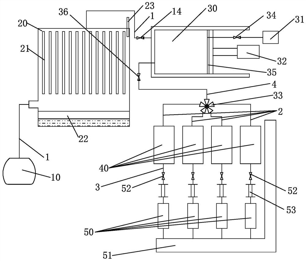
[0020] see Figure 1-2 , A boiler flue gas detection device, comprising a flue gas sampling mechanism, a dehumidification cooling mechanism, a flue gas separation mechanism, a flue gas storage mechanism, a flue gas detection mechanism, a connecting pipeline, and a control mechanism.
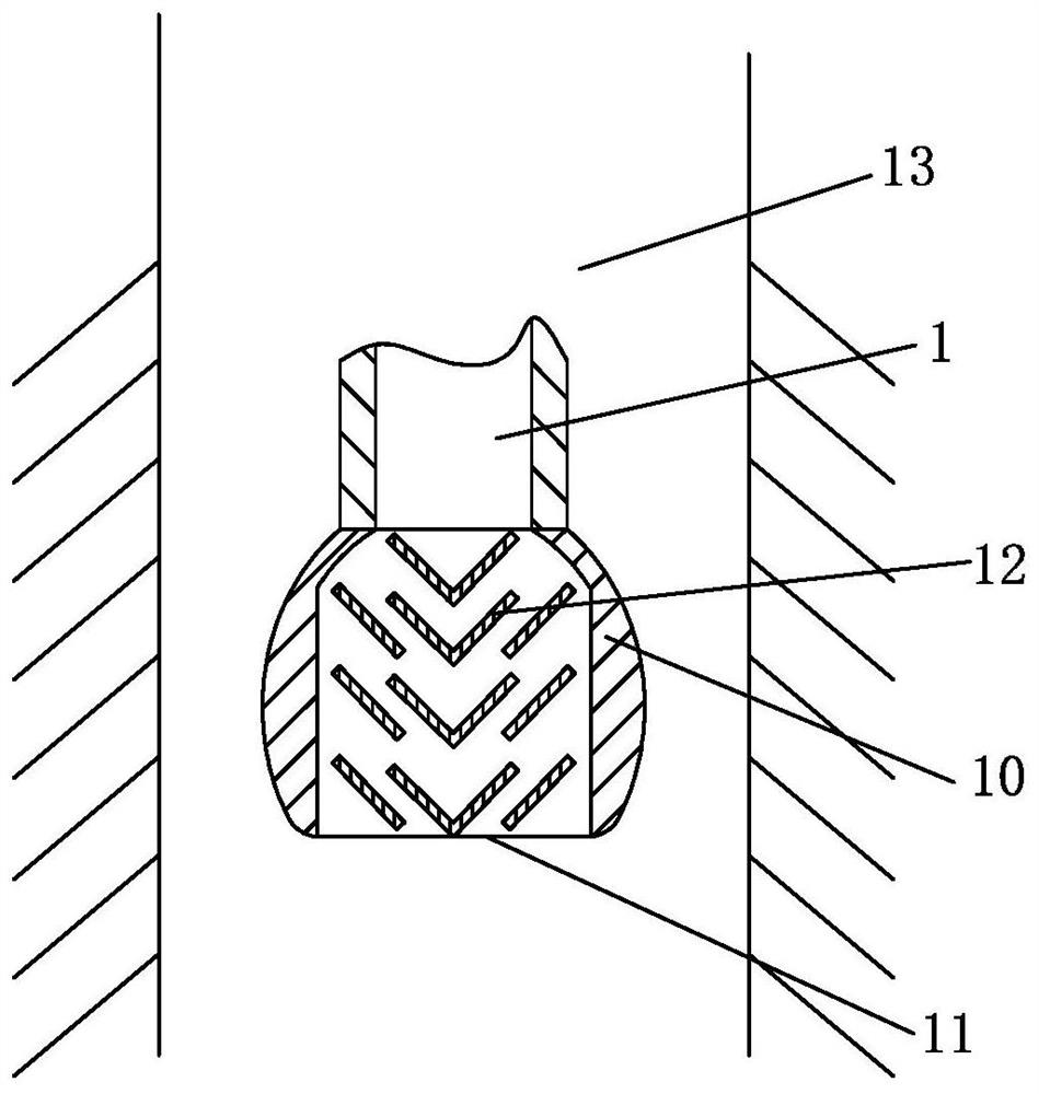
[0021] The flue gas sampling mechanism is used for extracting flue gas, and includes a sampling box 10 that can be arranged in the flue 13. The sampling box 10 is provided with a sampling port 11 at the bottom, and the sampling box 10 is provided with several inclined planes. Arranged baffles 12 . The dehumidification and cooling mechanism is used for removing moisture in the flue gas, and at the same time, it can be used for reducing the temperature of the flue gas, so as to meet the detection requirements of the detector 50 . It includes a condensing box 20, a plurality of condensing plates 21 arranged in the condensing box 20, and a gap for flue gas flow is provided between the plurality of condensing plates 21. The gap between the condensing plates 21 preferably corresponds to the inlet and outlet of the flue gas located in the condensing box 20, so that the flue gas flowing through the condensing box 20 can contact the condensing plate 21 in the largest area, so as to improve the condensation temperature and remove moisture. Effect.
[0022] The flue gas separation mechanism is used to inhale the flue gas and press the flue gas into the storage cylinder 40 . 31. A third valve body is arranged between the air pump 31 and the air extraction cavity 30, and a piston propeller 32 is arranged in the air extraction cavity 30. The piston propeller 32 includes a piston 35 and an air pressure, a hydraulic rod or a lead screw, and a driving motor structure for driving the piston 35. The air pump 31 is connected to the piston 35, and the piston is provided with a connection to the air pump 31. For the air suction hole, a third valve body 34 is provided between the air suction pump 31 and the piston. The flue gas storage mechanism is used to temporarily store the collected flue gas, and ensures a certain pressure, and includes an appropriate number of flue gas storage cylinders 40, and the appropriate number is at least the quantity for detecting the corresponding measurement gas type. The smoke detection mechanism includes a detector 50 for detecting the corresponding gas. The inlet end of the detector 50 is connected to the storage cylinder 40 of the smoke storage mechanism. The other end of the detector 50 is provided with a pipeline. Exhaust pipe 51 . The connecting pipeline includes a first pipeline 1 connecting the sampling box 10, the condensing box 20, and the air extraction cavity 30 in sequence, and the second pipeline 2 connecting the air extraction cavity 30 and each storage cylinder 40, The third pipeline 3 connecting the corresponding storage cylinder 40 and the corresponding detector 50, a second pipeline 2 is provided between each storage cylinder 40 and the air extraction cavity 30, and each second pipeline 2 There is a first valve body 52 for controlling the flow of flue gas from the storage cylinder 40 to the detector 50 . The first pipeline 1 is provided with a fourth valve body 14, and the fourth valve body 14 can be arranged anywhere on the first pipeline 1. In this embodiment, the fourth valve body 14 is arranged in the condensing tank between the body 20 and the air extraction cavity 30 . The control mechanism is used to control the operation of each mechanism and the on-off of the valve body according to the detection program or process.
[0023] The volume of the extraction cavity 30 is 1.5-10 times the volume of each storage cylinder 40, so that the smoke is forced into the storage cylinder 40 through the piston pusher 32 in the extraction cavity 30, so that The flue gas in the storage cylinder 40 has a certain air pressure, and can enter the corresponding detector 50 through the air pressure.
[0024] A flow meter 53 is provided on the second pipeline 2 between the detector 50 and the storage cylinder 40 .
[0025] It also includes an exhaust pipe 51, the exhaust port pipeline of the detector 50 is connected to the exhaust pipe 51, and the exhaust pipe 51 is provided with a negative pressure.
[0026] Several condensing plates 21 in the condensing box 20 are arranged up and down, the bottom of the condensing box 20 is provided with a liquid storage box 22 , and the several condensing plates 21 are suspended above the liquid storage box 22 .
[0027] The baffles 12 in the sampling box 10 are staggered.
[0028] A temperature sensor 23 is also provided in the condensation box 20 .
[0029] The air extraction cavity 30 is connected with a fourth pipeline 4, the fourth pipeline 4 is provided with a multi-way valve 33, and the corresponding second pipeline 2 is connected to the corresponding multi-way valve. output port. The second valve body 36 is disposed on the fourth pipeline 4 . The multi-way valve 33 can be controlled by manual or control mechanism to communicate with the corresponding second pipeline 2 . In this embodiment, four second pipeline 2, storage cylinder 40, and detector 50 are provided as an example, and the four detectors are O2, CO, NO, and CO2 detectors respectively. The state-of-the-art detector detects the corresponding gas content, and the final detection data is collected by the control mechanism.
[0030] The edge contour of the sampling box 10 is arc-shaped, so that the sampling box 10 can be put into the flue 13 or taken out from the flue 13 quickly.
[0031] In order to facilitate control and use, the above-mentioned first, second, third and fourth valve bodies 52, 36, 34, and 14 can be one-way valves.
[0032] The present invention will be further explained below in conjunction with the use principle of the device of the present invention.
[0033] see Figure 1-2, when in use, the piston 35 of the piston propeller 32 retreats, so that the air extraction cavity 30 is empty, the sampling box 10 of the flue gas sampling mechanism is placed in the flue 13, the air extraction pump 31 is activated by the control mechanism, and the third, The four valve bodies 34 and 14, the air pump 31 works, first the air pump 31 will extract the air in the air chamber 30, so that the air in the air chamber 30 becomes negative pressure, so that the sampling port 11 through the air pump 13 will extract the air in the flue 13. The flue gas passes through the sampling box 10 and passes through the condensing box 20 to cool and remove moisture, and the water vapor in the flue gas contacts the condensing plate 21 in the condensing box 20, and is cooled and condensed into water and drips along the condensing plate 21. Inside the water box 22 . The control mechanism can detect the temperature in the condensing box through the temperature sensor 23 in the condensing box 20, so as to further control the temperature of the flue gas by controlling the cooling speed of the condensing box 20, and the flue gas enters the extraction cavity 30 after dehumidification and cooling. , the suction pump 31 continues to work, so that the smoke continuously enters the suction cavity 30 and is discharged through the suction pump 31, so as to form a continuous flow of smoke in the suction cavity 30, so that the air can be completely discharged from the suction cavity 30 away.
[0034] According to the test data of specific equipment. After the time when the air can be completely discharged from the air extraction cavity 30, or at least the time when the detection result of the corresponding gas in the flue gas is not affected. The control mechanism closes the third and fourth valve bodies 34 and 14, and opens the second valve body 36. The control mechanism controls the corresponding driving structure of the piston propeller 32 to drive the piston 35 to advance, and the gas in the pumping cavity 30 passes through the fourth pipeline. 4. Control the multi-way valve 33 to push out all the smoke in the extraction cavity 30. After the pushed out flue gas passes through the corresponding second pipeline 2 and finally enters the storage cylinder 40 connected to the corresponding second pipeline 2, the control mechanism controls the second valve body 36 to close, and then the control mechanism controls the piston pusher 32 to drive accordingly The structure drives the piston 35 to retreat, and the retracted piston 35 generates a negative pressure in the extraction chamber 30, and continues to inhale the flue gas from the sampling box 10 through the condensing box 20. If necessary, the third valve body 34 can be opened to pass the extraction pump 31 Exhale further. When the air extraction cavity 30 is filled up again, the multi-way valve 33 can be controlled by the control mechanism to switch to another second pipeline, and the corresponding storage cylinders 40 can be inflated in sequence, and all the storage cylinders 40 can be filled one by one as needed. .
[0035] If gas detection is required, the first valve body 52 on one or more third pipelines 3 can be opened by the control mechanism. There will be a certain air pressure. After opening the corresponding first valve body 52 , the flue gas in the corresponding storage cylinder 40 will enter the corresponding detector 50 for detection, and the residual gas after detection will be discharged from the exhaust pipe 51 . Each detector does not interfere with each other during the detection process. Multiple gas detections can be completed at one time.
[0036] The above-mentioned application of the present invention is only part of the embodiments of the present invention, and does not limit the present invention in any form. The enumeration of the embodiments of the present invention is not intended to limit the protection scope of the present invention. Any person skilled in the art, without departing from the scope of the technical solution of the present invention, uses the technical content or enlightenment disclosed in the present invention to make changes to equivalent implementation cases of equivalent changes, which have not yet departed from the technical solution content of the present invention. Any simple modifications, equivalent changes and modifications that are substantially the same as those of the present invention still fall within the scope of the technical solutions of the present invention.