Fixed bed desulfurization reaction device and use method thereof

A technology of reaction device and fixed bed, which is applied in the field of fixed bed desulfurization reaction device, can solve the problems of low fluency of added materials, low utilization efficiency of desulfurization agent, and large resistance consumption of the device, so as to improve the utilization rate of desulfurization agent and improve The smoothness of blanking and the effect of eliminating the dead angle of refueling

Active Publication Date: 2021-06-01
SHANDONG SHANDA WIT ENVIRONMENTAL ENGINEERING CO LTD
View PDF5 Cites 0 Cited by
  • Summary
  • Abstract
  • Description
  • Claims
  • Application Information

AI Technical Summary

Problems solved by technology

[0005] Aiming at some deficiencies in the existing technology, such as low fluidity of added materials, low utilization efficiency of desulfurization agent, large resistance consumption of the device, poor dust removal performance, etc.

Method used


Image

  • Fixed bed desulfurization reaction device and use method thereof
  • Fixed bed desulfurization reaction device and use method thereof
  • Fixed bed desulfurization reaction device and use method thereof

Examples


Embodiment 1

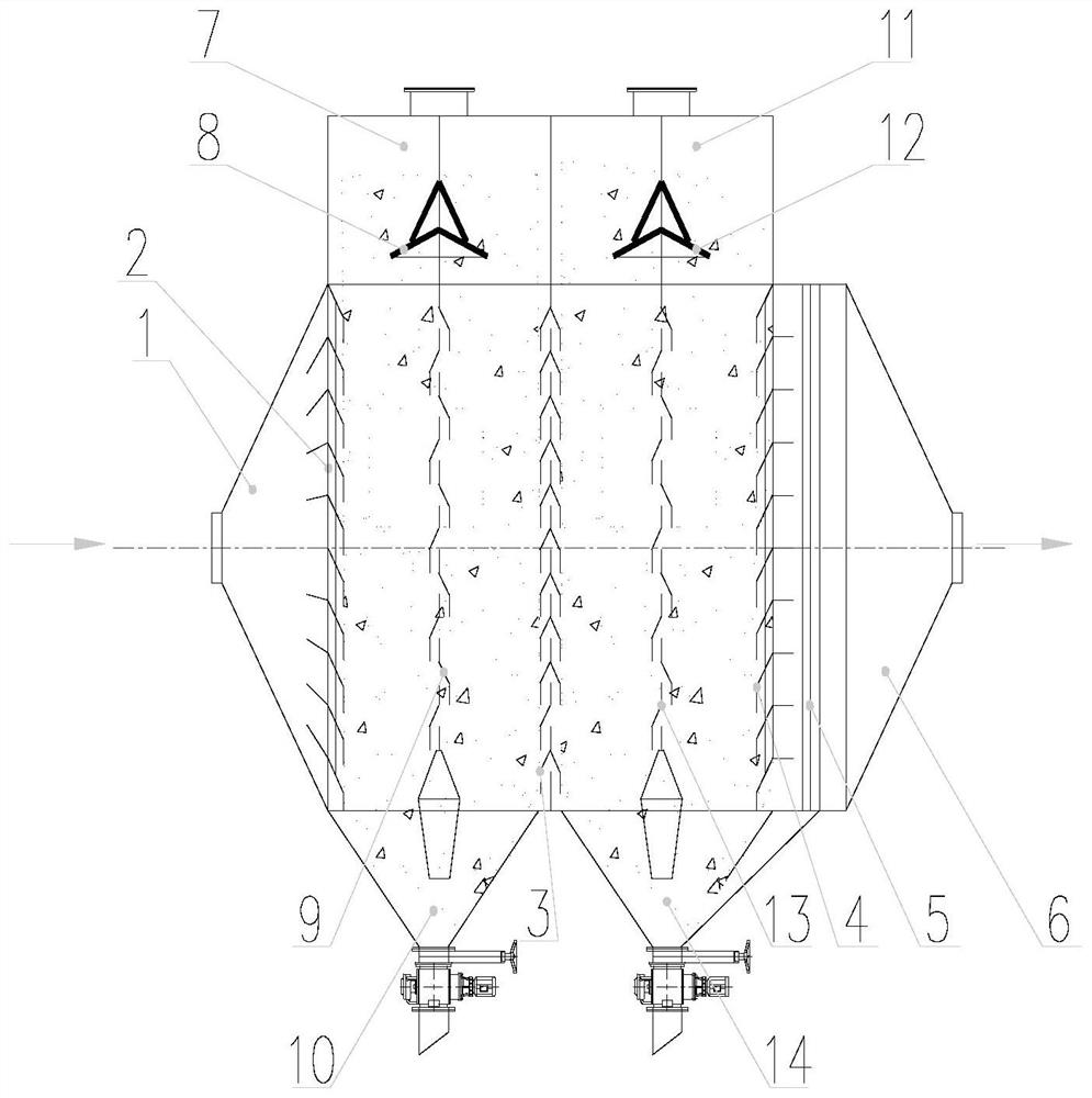
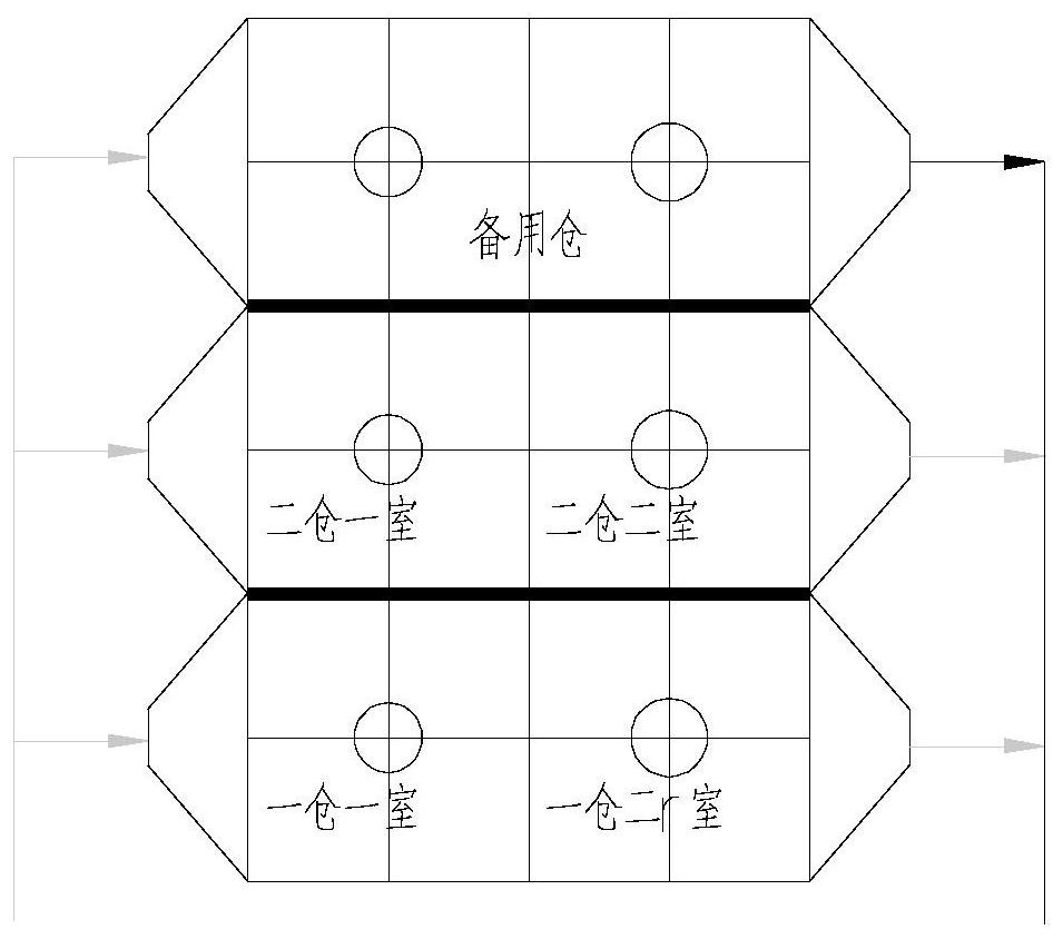
[0067] Such as figure 1 As shown, this embodiment provides a fixed bed desulfurization reaction process. The overall process route is to enter the flue gas inlet 1 of each warehouse first, enter the reaction chamber through the inlet grid diversion wall 2 for desulfurization reaction, and then enter the next reaction chamber through the inter-chamber grid diversion wall 3 , and then the gas that reaches the standard is discharged through the outlet grid guide partition wall 4, the outlet groove plate 5, and the flue gas outlet 6 in sequence.

[0068] The specific process route includes the following steps:

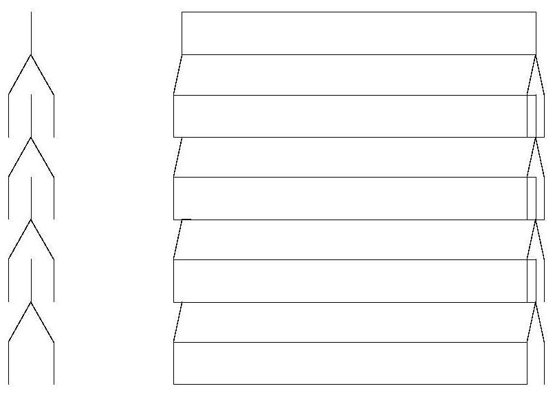
[0069] 1) The raw flue gas to be treated enters through the flue gas inlet 1, and then passes through the inlet grid to divert the partition wall 2. The angle of the deflector at the front end of the module of the inlet grid diversion partition wall 2 fits the flue gas flow field, so that the flue gas can pass through smoothly and completely isolate the closed materials ...

Embodiment 2

[0075] This embodiment provides a blanking process, which includes the following steps: the desulfurizer filling process is arranged vertically, and the layout of the first room and the second room is the same. Taking the first room as an example, it enters from the material dosing section 7 at the top of the device, and passes through Butterfly buffer material guide 8 evenly distributes the material into the warehouse, and after the material fails, it can be discharged through the discharge system 10 at the lower part. A blanking stabilizer 9 is arranged in the warehouse to ensure that the blanking is smooth and the material layer is uniform.


PUM


Abstract

The invention relates to the field of flue gas treatment, and in particular, relates to a fixed bed desulfurization reaction device and a use method thereof. The fixed bed desulfurization reaction device comprises a desulfurization bin, and the interior of the desulfurization bin is divided into a plurality of desulfurization chambers which are connected in series in the horizontal direction by inter-chamber mesh diversion partition walls; a desulfurizing agent feeding section is arranged at the top of the desulfurizing bin, a plurality of desulfurizing agent feeding sites are arranged in the desulfurizing agent feeding section, each desulfurizing chamber at least corresponds to one desulfurizing agent feeding site, and each desulfurizing agent feeding site corresponds to one butterfly-shaped buffering material guide device and one discharging stabilizer; and two ends of the desulfurization bin in the horizontal direction are respectively provided with a flue gas inlet and a flue gas outlet, the flue gas inlet and the flue gas outlet are neck-expanded structures, and inlet and outlet mesh guide partition walls are arranged at the joints of the neck-expanded structures and the desulfurization bin. The device mainly aims at overcoming the defects that in the prior art, material adding and discharging fluency is not high, the utilization efficiency of a desulfurizing agent is low, device resistance consumption is large, and dust removal performance is poor.

Description

technical field [0001] The disclosure relates to the field of flue gas treatment, in particular to a fixed-bed desulfurization reaction device and a method for using the same. Background technique [0002] The statements herein merely provide background information related to the present disclosure and may not necessarily constitute prior art. [0003] At present, common flue gas desulfurization methods include wet method, semi-dry method, dry method and so on. Wet desulfurization is stable in operation and high in desulfurization efficiency, but desulfurization wastewater is difficult to treat, white smoke is serious, and the system is complex, requiring heavy workload for operation and maintenance; semi-dry desulfurization process is also widely used, with high desulfurization efficiency, but there is operational resistance Large, difficult to adapt to high humidity flue gas and other shortcomings. Dry desulfurization does not require water and has no white smoke phenome...

Claims


Application Information

Patent Timeline
Patent Type & Authority Applications(China)
IPC IPC(8): B01D53/82B01D53/48
CPCB01D53/82B01D53/48B01D2258/0283Y02A50/20
Inventor 刘畅展茂源毕德刚孙玉翠辛继长金家国师炜肖海河
Owner SHANDONG SHANDA WIT ENVIRONMENTAL ENGINEERING CO LTD
Why Eureka
Try Eureka