Optical module in-mold copper inlaying die-casting molding mechanism

A technology of die-casting and optical modules, which is applied in the field of die-casting equipment and molds, can solve the problems of easy deformation of the shell, low production efficiency, high defect rate, etc., and achieve the effect of improving tightness

Pending Publication Date: 2021-06-01
深圳市宝田精工科技有限公司
View PDF0 Cites 1 Cited by
  • Summary
  • Abstract
  • Description
  • Claims
  • Application Information

AI Technical Summary

Problems solved by technology

This connection method has many disadvantages in the production process. For example, the soldering process needs to go through a high-temperature conveyor furnace, the shell is easily deformed, and the defect rate is relatively high; secondly, the soldering process is prone to environmental pollution; thirdly, due to the There is non-aggregation between materials in the connection between alloy & aluminum alloy, and the connection through soldering often causes the shell to separate from the copper
It can be seen that the soldering process has low yield, low production efficiency, high cost, and serious safety hazards

Method used


Image

  • Optical module in-mold copper inlaying die-casting molding mechanism
  • Optical module in-mold copper inlaying die-casting molding mechanism
  • Optical module in-mold copper inlaying die-casting molding mechanism

Examples


Embodiment Construction

[0048] The following will clearly and completely describe the technical solutions in the embodiments of the present invention with reference to the accompanying drawings in the embodiments of the present invention. Obviously, the described embodiments are only part of the embodiments of the present invention, not all of them. Based on the embodiments of the present invention, all other embodiments obtained by persons of ordinary skill in the art without creative efforts fall within the protection scope of the present invention.

[0049] It should be noted that all directional indications (such as up, down, left, right, front, back...) in the embodiments of the present invention are only used to explain the relationship between the components in a certain posture (as shown in the accompanying drawings). Relative positional relationship, movement conditions, etc., if the specific posture changes, the directional indication will also change accordingly.

[0050] In addition, the ...


PUM


Abstract

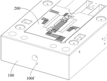
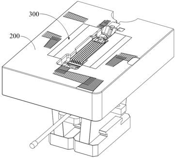
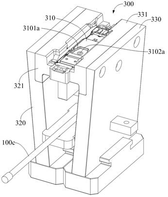
The invention discloses an optical module in-mold copper inlaying die-casting molding mechanism. The mechanism is characterized in that a molding insert is arranged in a mold core main body, and a clamping groove is concavely formed in the molding surface of the molding insert, so that a copper block can be clamped on the molding insert, meanwhile, a ventilation block is arranged in an assembly groove of a movable mold plate, a first gas path is arranged in the ventilation block, a second gas path communicated with the first gas path is arranged in the molding insert, a third gas path communicated with the first gas path is arranged on the movable mold plate, and the third gas path is connected with an external negative pressure generator through a gas pipe. Therefore, negative pressure can be guided into the clamping groove through the air paths to quickly adsorb and fix a copper block insert, and copper block and zinc alloy& aluminum alloy optical module embedding and joint can be achieved through die-casting fit, so that the production efficiency and the yield of a copper-embedded optical module shell are greatly improved, and a good market prospect is provided for production and application of an optical module in the field of precision die casting.

Description

technical field [0001] The invention relates to the technical field of die-casting equipment and moulds, in particular to a die-casting mechanism for inlaying copper in an optical module mold. Background technique [0002] With the advancement of science and technology, a large number of high-conductivity materials have been widely used. Due to their physical properties, most materials have high melting points, and it is difficult to realize them in batches with the current technology. [0003] For example, the thermal conductivity of zinc alloy is about 110W / m K, which is already at the ceiling stage in the field of high-power and high-thermal conductivity of 5G optical modules, while the thermal conductivity of copper alloy is much higher than that of zinc alloy and aluminum alloy, and the thermal conductivity of copper alloy is 397W / m K. m·K or so. However, pure copper has a high melting point, about 1000°C, making it difficult to manufacture, and there are many factors ...

Claims


Application Information

Patent Timeline
Patent Type & Authority Applications(China)
IPC IPC(8): B22D17/22B22D17/24B22D19/16
CPCB22D17/22B22D17/24B22D19/16
Inventor 陈荣才汪仁国
Owner 深圳市宝田精工科技有限公司
Why Eureka
Try Eureka