Method for achieving high-speed cutting on center lathe and multifunctional machine head

A common lathe, high-speed cutting technology, applied to metal processing machinery parts, clamping, support, etc., can solve the problems of poor product quality, slow speed of common lathes, low processing accuracy, etc., to improve processing efficiency and quality, and save equipment The effect of purchasing cost and guaranteeing machining accuracy

Inactive Publication Date: 2021-06-01
HUBEI HANGPENG CHEM POWER TECH
View PDF10 Cites 0 Cited by
  • Summary
  • Abstract
  • Description
  • Claims
  • Application Information

AI Technical Summary

Problems solved by technology

[0003] Aiming at the technical problems existing in the prior art, the present invention provides a method for realizing high-speed cutting on an ordi

Method used


Image

  • Method for achieving high-speed cutting on center lathe and multifunctional machine head
  • Method for achieving high-speed cutting on center lathe and multifunctional machine head
  • Method for achieving high-speed cutting on center lathe and multifunctional machine head

Examples


Embodiment 1

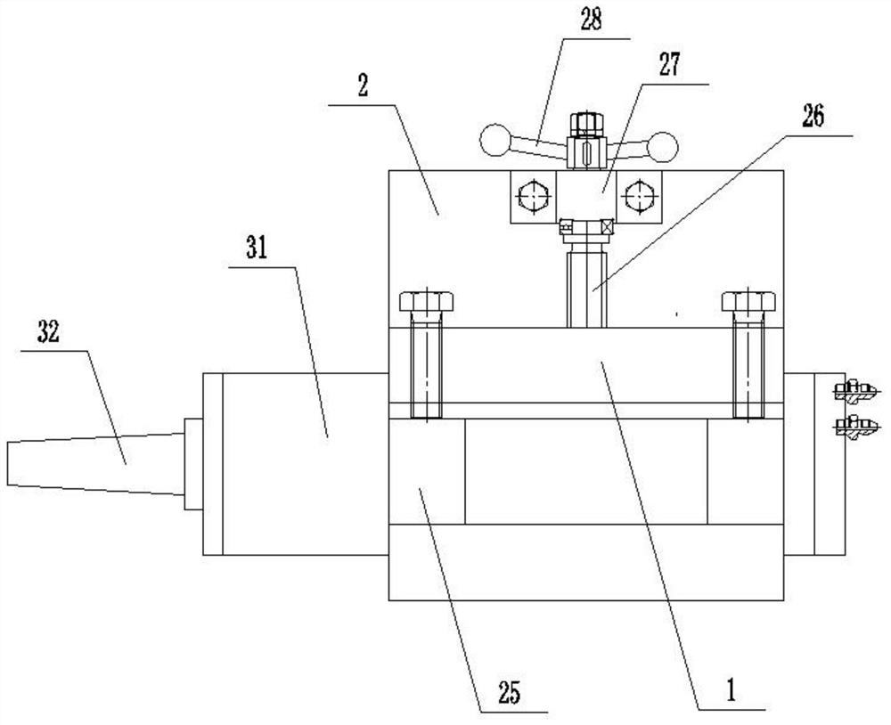
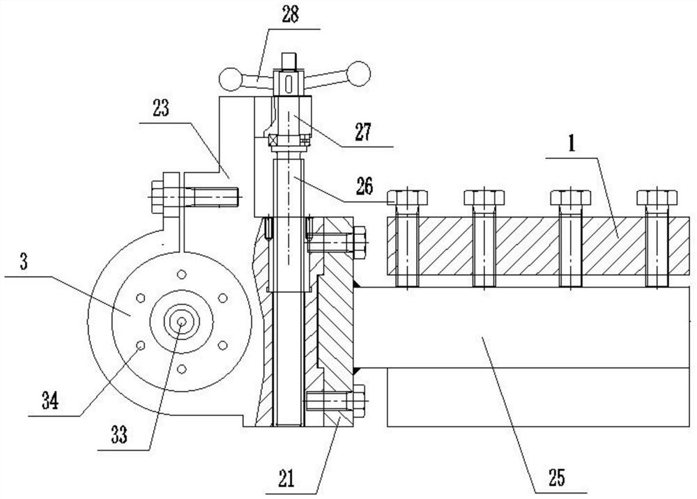
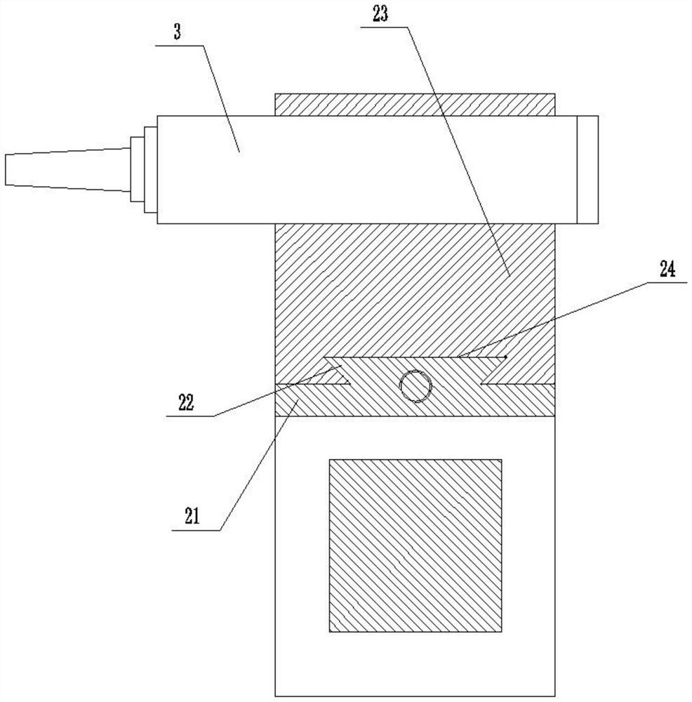
[0038] A multifunctional handpiece, such as Figure 1 ~ Figure 3 As shown, it includes a base 2 and an electric spindle 3 . The base 2 includes a first base 21 and a second base 23 , and the electric spindle 3 is installed on the second base 23 . The side of the first base 21 close to the second base 23 is provided with a slide block 22, the side of the second base 23 close to the first base 21 is provided with a slide groove 24, the slide block 22 is slidably arranged in the slide groove 24, and The chute 24 extends vertically, so that the slider 22 can slide vertically in the chute 24 . The cross sections of the chute 24 and the slider 22 are both dovetail-shaped, so that the slider 22 is clamped in the chute 24 to prevent the slider 22 from detaching from the opening of the chute 24 . The first base 21 is also provided with a fixed bracket 25 away from the side of the second base 23, and the fixed bracket 25 is fixed on the square tool rest 1 of the ordinary lathe by bolt...

Embodiment 2

[0047] A high-speed grinding head, such as Figure 4 As shown, it includes the multifunctional machine head of Embodiment 1, and also includes a grinding tool. The grinding tool includes a grinding wheel cover 41 , a grinding wheel 43 , a grinding wheel outer baffle 44 and a first nut 45 . The grinding wheel cover 41 is sleeved on the rotating shaft 32 of the electric spindle 3 , and the slope of the inner wall of the grinding wheel cover 41 matches the slope of the side wall of the rotating shaft 32 , limiting the insertion distance of the grinding wheel cover 41 on the rotating shaft 32 . The grinding wheel 43 and the grinding wheel outer baffle 44 are sleeved on the grinding wheel cover 41, and the end of the grinding wheel cover 41 close to the housing 31 of the electric spindle 3 is integrally provided with the grinding wheel inner baffle 32, and the grinding wheel outer baffle 44 is located in the grinding wheel 43 away from the grinding wheel. One side of the baffle 42...

Embodiment 3

[0050] A high-speed inner hole grinding machine head, such as Figure 5 As shown, it includes the multifunctional head of Embodiment 1, and also includes a long rod sleeve device and an inner hole grinding tool.

[0051] The long rod sleeve device includes a transmission long shaft 51 and a sleeve 52 . One end of the long transmission shaft 51 is screwed into the threaded hole 33 at the end of the rotating shaft 32 . The sleeve 52 is sheathed outside the long drive shaft 51 , and one end of the sleeve 52 is fixed to the mounting hole 34 at the end of the housing 31 by a bolt, and an abutting groove 58 is provided on the outer wall of the other end of the sleeve. The rotating shaft 32 can drive the transmission long rod 51 to rotate, and the long rod sleeve device plays the role of extending the rotating shaft 32 .

[0052] The long drive shaft 51 is also sleeved with a lock nut 53 and an inner retaining ring 55, each of the two ends of the inner retaining ring 55 is closely ...


PUM


Abstract

The invention relates to a method for achieving high-speed cutting on a center lathe and a multifunctional machine head. The multifunctional machine head comprises a base and an electric spindle axially and horizontally installed on the base. A fixed support is further installed on the base and used for being connected with a square tool rest of the center lathe. The electric spindle comprises a shell, a rotating shaft and a driving mechanism. The shell is mounted on the base. The rotating shaft extends out of one end face of the shell and is rotatably connected with the shell, and at least two mounting holes are further formed in the end face of the shell. The driving mechanism is mounted in the shell and drives the rotating shaft to rotate. The area of the cross section of the rotating shaft is gradually reduced towards the end, and a threaded hole is formed in the end face of the rotating shaft and shares the same axis with the rotating shaft. High-speed milling, drilling, boring and grinding functions can be achieved on the center lathe, the machining precision is ensured, the machining efficiency and quality are improved, and the equipment acquisition cost is saved.

Description

technical field [0001] The invention relates to the technical field of high-speed cutting, in particular to a method for realizing high-speed cutting on an ordinary lathe and a multifunctional machine head. Background technique [0002] The development trend of machining is high efficiency, high precision, high flexibility and greening. High-speed cutting and high-speed machining are an advanced manufacturing technology that has risen rapidly in the past two decades. High-speed machining has been widely used in industrially developed countries, and has become the key technology for processing integral structural parts, complex parts and product modification in aerospace, automobile, and mold manufacturing industries, as well as the mainstream direction of modern machining technology development. However, the price of commercialized high-speed machine tools is high. For enterprises that already have ordinary lathes, the cost of purchasing high-speed machine tools is too high...

Claims


Application Information

Patent Timeline
IPC IPC(8): B23Q3/00B23Q37/00
CPCB23Q37/00B23Q3/00
Inventor 葛卫曹明保徐纪华朱学军陈魏平
Owner HUBEI HANGPENG CHEM POWER TECH
Why Eureka
Try Eureka