Ultra-large plastic tube fusion-splicing equipment used for intelligent manufacturing production line
A technology of intelligent manufacturing and welding equipment, which is applied in the field of welding equipment, can solve the problems of difficult control of pressure, poor welding quality, and more manpower consumption, so as to improve the effect of hot melting, reduce labor intensity, and ensure flatness.
- Summary
- Abstract
- Description
- Claims
- Application Information
AI Technical Summary
Problems solved by technology
Method used
Image

Examples
Embodiment 1
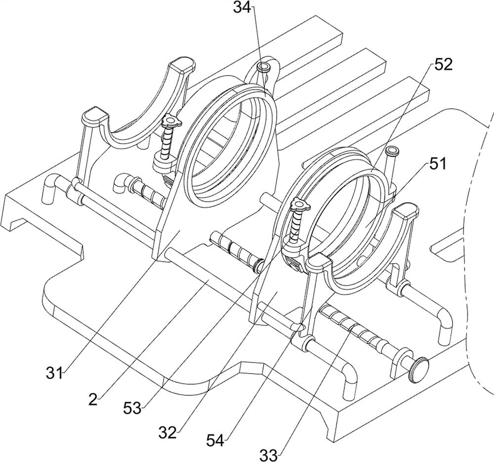
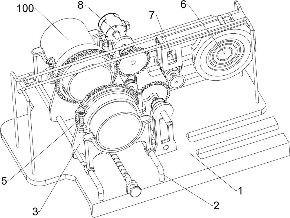
[0027] A super-large plastic pipe welding equipment for intelligent manufacturing production line, such as figure 1 , figure 2 and Figure 4 As shown, it includes a base 1, a first guide rail 2, a moving assembly 3, a clamping assembly 5, and a hot-melt assembly 6. Two first guide rails 2 are connected to the left side of the top of the base 1. Between the base 1 and the first guide rail 2 A moving assembly 3 is connected, a clamping assembly 5 is connected to the moving assembly 3 , and a hot-melt assembly 6 is connected in the middle of the top of the base 1 .
[0028] The mobile assembly 3 includes a first slide rail 31, a second slide rail 32, a two-way threaded rod 33 and an annular slider 34, and the first slide rail 31 is slidably connected between the rear sides of the two first guide rails 2, and the two A second slide rail 32 is slidably connected between the front sides of the first guide rail 2, a two-way threaded rod 33 is connected to the left side of the top ...
Embodiment 2
[0033] On the basis of Example 1, such as Figure 4 As shown, a cutting assembly 7 is also included. The cutting assembly 7 includes a mounting frame 71, a biaxial motor 72 and a cutting disc 73. The bottom left side of the slide plate 64 is connected to the mounting frame 71, and the bottom of the mounting frame 71 is connected to the biaxial motor 72. , the two output shafts of the biaxial motor 72 are connected with a cutting disc 73 .
[0034] When the plastic pipe 100 is fixed on the inside of the first supporting plate 51 and the arc splint 52, the biaxial motor 72 is started to work, and the biaxial motor 72 works to drive the cutting disc 73 to rotate, and then the slide plate 64 is manually pushed to move to the left, passing through the cutting disc 73 The end of plastic pipe 100 is cut, when plastic pipe 100 is cut, plastic pipe 100 can be rotated artificially, and plastic pipe 100 rotates and drives first supporting plate 51, arc splint 52 and annular slide block 3...
Embodiment 3
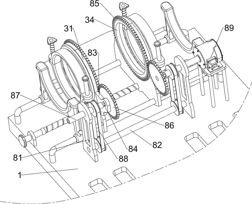
[0036] On the basis of Example 2, such as image 3As shown, a rotating assembly 8 is also included, and the rotating assembly 8 includes a fixed plate 81, a shaft rod 82, a connecting plate 83, a diamond rod 84, a ring gear 85, a driving gear 86, an inner diamond sleeve 87, a belt transmission group 88 and Geared motor 89, the front and rear both sides of base 1 middle part are all connected with fixed plate 81, between the bottom of both sides fixed plate 81 is connected with shaft rod 82 in a rotational manner, the right end of first slide rail 31 and the second slide rail 32 are all connected to each other. Connecting plate 83 is connected, and connecting plate 83 is rotatably connected with rhombic rod 84, ring gear 85 is connected to the outer side of annular slider 34, and one end of rhomboid rod 84 is connected with driving gear 86, and driving gear 86 meshes with ring gear 85 , the upper part of the fixed plate 81 is rotatably connected with an inner diamond-shaped sle...
PUM
 Abstract
Description
Claims
Application Information
 - R&D Engineer
- R&D Manager
- IP Professional
- Industry Leading Data Capabilities
- Powerful AI technology
- Patent DNA Extraction
Browse by: Latest US Patents, China's latest patents, Technical Efficacy Thesaurus, Application Domain, Technology Topic.
© 2024 PatSnap. All rights reserved.Legal|Privacy policy|Modern Slavery Act Transparency Statement|Sitemap