Connector for electrolytic powder processing, electrolytic powder processing device and manufacturing method

A powder making device and connector technology, which is applied in the direction of connection, coupling device, electrolytic components, etc., can solve the problems of unsatisfactory long-term continuous use, relatively high requirements for the flatness of the pole plate, and the inconvenient movement of the pole plate, etc., to achieve Simple and convenient installation, good contact, and the effect of reducing contact voltage

Inactive Publication Date: 2021-06-01
有研纳微新材料(北京)有限公司
View PDF10 Cites 0 Cited by
  • Summary
  • Abstract
  • Description
  • Claims
  • Application Information

AI Technical Summary

Problems solved by technology

Although the above method can reduce the contact voltage, the flatness of the plate is relatively high, the plate cannot be easily moved, the operation is cumbersome, and the effect of continuous use for a long time is not ideal.

Method used


Image

  • Connector for electrolytic powder processing, electrolytic powder processing device and manufacturing method
  • Connector for electrolytic powder processing, electrolytic powder processing device and manufacturing method

Examples


Embodiment 1

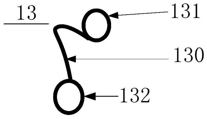
[0030] 200 pure copper wires with a diameter of 1mm and a length of 500mm are used as the flexible conductive body 130, and the two ends are placed in a pure copper tube with an inner hole of 10.5mm, a length of 20mm, and a wall thickness of 2mm (as the first fixed end 131 or the second fixed end. 132), and then through 900°C and 100MPa hot pressing, the copper wire and copper tube are welded into a connector 13 of 8*30*20mm, and the allowable current of this connector is no more than 2000A.

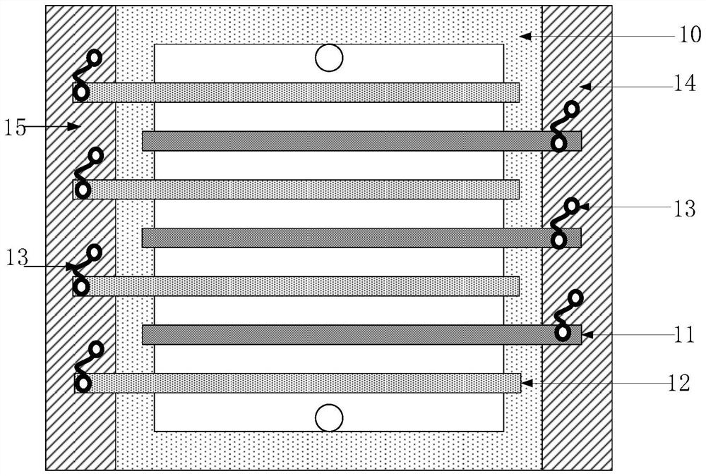
[0031] Please refer to Figure 1-2 , the electrolytic cell 10 is filled with an electrolyte solution, and under the conditions of the electrolytic copper powder with the voltage of the electrolytic cell 10 being 2.03V, 3000A, three cathode plates 11 and four anode plates 12, the cathode plate 11 of the commonly used direct lapping method is adopted The contact voltage with the first conductive busbar is 0.09-0.11V, and the connector 13 of the present invention is used instead, wherein th...

Embodiment 2

[0034] The surface of the first fixed end 131 of the connector 13, the second fixed end 132 and the contact part of the pole plate and the conductive bus bar are coated with a layer of conductive paste, and other conditions are the same as in Example 1, the cathode plate 11 and the first conductive bus bar 14 The contact voltage drop is 0.01-0.02V, the average drop is 85%, and the energy consumption is reduced by 4.2%.

Embodiment 3

[0036] The surface of the first fixed end 131 of the connector 13, the second fixed end 132 and the contact part of the pole plate and the conductive bus bar are coated with a layer of conductive paste, and a U-shaped stainless steel block (thickness 10mm, the size ratio of the U-shaped groove is fixed) 0.05-0.1mm) and heating to 400-500°C, directly fix the fixing member and the pole plate (or conductive busbar) together, and other conditions are the same as in embodiment 1. The contact voltage drop between the cathode plate 11 and the conductive busbar is 0.00-0.01V, with an average drop rate of 95%, and the energy consumption is reduced by 4.7%.


PUM

PropertyMeasurementUnit
thicknessaaaaaaaaaa

Abstract

The invention relates to the field of electrolytic powder processing, in particular to a connector for electrolytic powder processing, an electrolytic powder processing device and a manufacturing method. The connector comprises a flexible conductive body, a first fixing end and a second fixing end, wherein the first fixing end is used for connecting the flexible conductive body with a conductive busbar of the electrolytic powder processing device; and the second fixing end is used for connecting the flexible conductive body with a polar plate of the electrolytic powder processing device. The polar plate and the conductive busbar are connected together by using the connector comprising the flexible conductive body and a fixing piece. The mounting is simple and convenient, the contact is good, the contact voltage can be reduced by 20-95%, and the energy consumption of electrolysis can be reduced by 1-10%. The electrolytic powder processing device is suitable for all electrolytic powder processing and electrolytic refining.

Description

technical field [0001] The present application relates to the technical field of electrolytic powder production, in particular to a connector for electrolytic powder production, an electrolytic powder production device and a manufacturing method. Background technique [0002] Electrolysis is a technology that uses electric energy to prepare metal or alloy powder or refine it. Generally, the current is relatively large, and there is a contact voltage between the conductive busbar and the plate, which accounts for about 2-12% of the power consumption, resulting in an increase in electrolysis energy consumption. At present, the contact surface between the pole plate and the conductive busbar is generally smoothed to increase the contact surface; Yang Guangdi and others proposed a socket connection, which can greatly reduce the contact voltage, but requires that the anode plate and the cathode plate are fixed (for details, see : Yang Guangdi. Electrolytic manganese socket conduc...

Claims


Application Information

Patent Timeline
Patent Type & Authority Applications(China)
IPC IPC(8): C25C5/00C25C7/02H01R4/02H01R31/06H01R43/02
CPCC25C5/00C25C7/02H01R31/06H01R4/02H01R43/02
Inventor 王林山胡强李楠楠汪礼敏王忠
Owner 有研纳微新材料(北京)有限公司
Why Eureka
Try Eureka