Light beam divergence angle deflection aperture secondary constraint display module

A beam divergence angle, secondary constraint technology, applied in optics, optical components, instruments, etc., can solve problems such as difficult to achieve small divergence angle beam projection of pixels or sub-pixels, to overcome focus-convergence conflicts, low noise, The effect of increasing the number

Active Publication Date: 2021-06-01
驻景(广州)科技有限公司
View PDF19 Cites 9 Cited by
  • Summary
  • Abstract
  • Description
  • Claims
  • Application Information

AI Technical Summary

Problems solved by technology

However, the existing 3D display methods and 3D display structures are difficult to realize the small divergence angle beam projection of pixels or sub-pixels, and the large viewing angle image reception of the observer's eyes.

Method used


Image

  • Light beam divergence angle deflection aperture secondary constraint display module
  • Light beam divergence angle deflection aperture secondary constraint display module
  • Light beam divergence angle deflection aperture secondary constraint display module

Examples


Embodiment 1

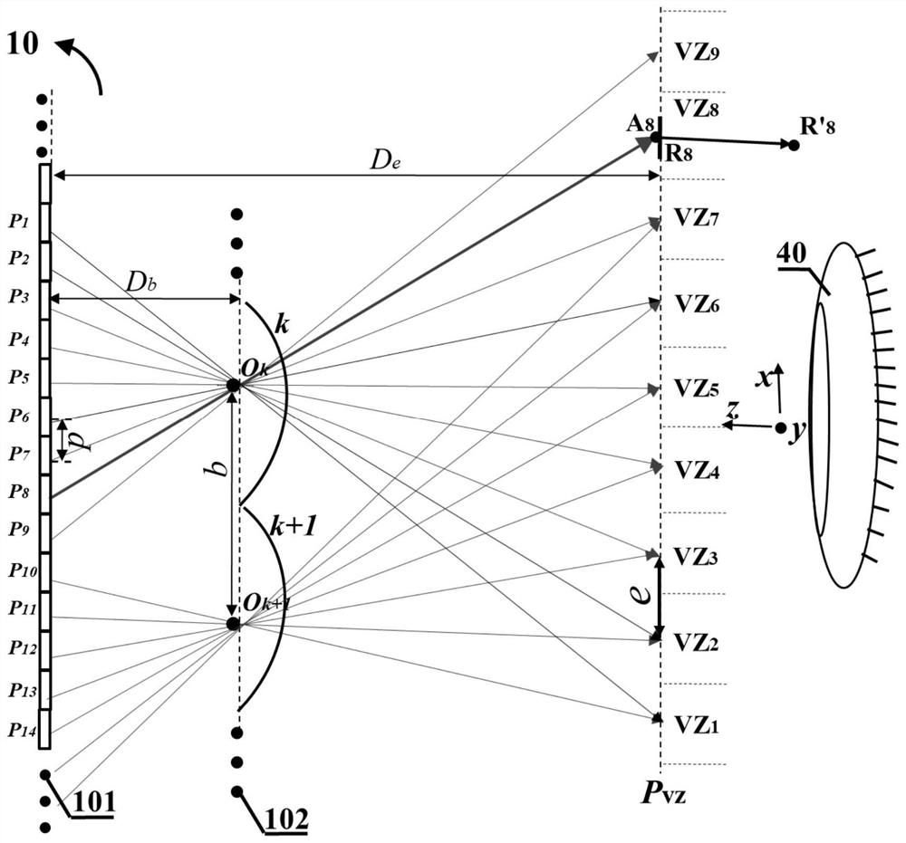
[0088] A cylindrical lens grating composed of a one-dimensional arrangement of cylindrical lenses as the grating unit is used as the spectroscopic device 102, such as image 3 shown. This type of optical splitting device is called a one-dimensional grating type optical splitting device 102 . For clarity of illustration, image 3 Only two grating units k and k+1 are shown, and some pixels p corresponding to the two grating units 1 ,p 2 ,p 3 ,p 4 ,p 5 ,p 6 ,p 7 ,p 8 ,p 9 ,p 10 ,p 11 ,p 12 ,p13 ,p 14 . The grating elements are arranged along the x direction. The optical center of the grating unit k and k+1 in the xz plane is expressed as O k and O k+1 . The display screen 101 and the light splitting device 102 constitute a multi-view display structure 10 . Wherein, b is the spacing between adjacent grating units along the x-direction of the arrangement direction of the grating units, p is the spacing between adjacent pixels on the display screen 101 along the x...

Embodiment 2

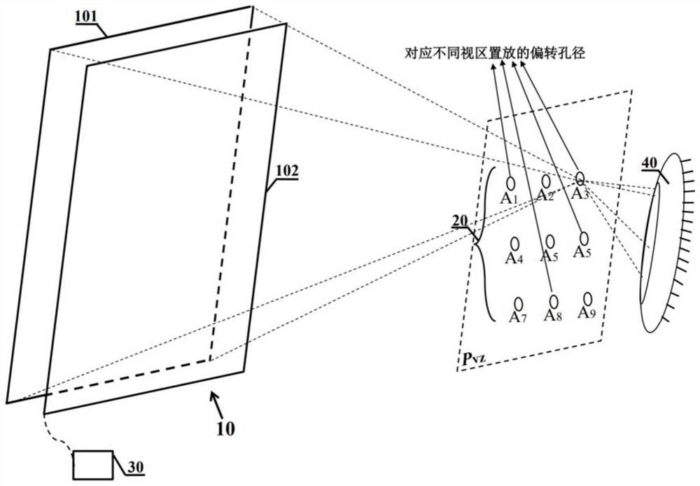
[0107] A microstructure array composed of microstructures is used as the light splitting device 102, such as Figure 27 shown. Each microstructure of the microstructure array type light splitting device 102 corresponds to each pixel of the display screen 101 one by one, and by deflecting the projection direction of the light beam from the corresponding pixel, different pixel groups on the display screen 101 are guided to project light to the corresponding viewing area respectively. information. The display screen 101 and the light splitting device 102 constitute a multi-view display structure 10 . The two-dimensional distribution of each viewing area, such as Figure 28 The 9 viewports shown: Viewport VZ 1 , view zone VZ 2 , view zone VZ 3 , view zone VZ 4 , view zone VZ 5 , view zone VZ 6 , view zone VZ 7 Viewport VZ 8 , view zone VZ 9, which are two-dimensionally arranged along the x and y directions. In one-to-one correspondence, the nine images are respectively...


PUM


Abstract

The invention discloses a light beam divergence angle deflection aperture secondary constraint display module. The light beam divergence angle deflection aperture secondary constraint display module comprises a multi-view display structure, a deflection aperture array and a control device. The multi-view display structure comprises a display screen, a light splitting device and a backlight source assembly for providing backlight when a backlight type display screen is adopted, and the light splitting device restrains and guides pixel groups or sub-pixel groups on the display screen to project light information to respective corresponding visual areas. According to the light beam divergence angle deflection aperture secondary constraint display module, the divergence angle of each light beam entering the eyes of an observer is secondarily constrained by using the size of the deflection aperture, and the problem that a view field is limited by a single deflection aperture is solved through a plurality of deflection apertures placed corresponding to a plurality of visual areas respectively. Furthermore, by introducing an orthogonal characteristic, cross-talk noise of projected light information of the display module is reduced, or / and the number of projection views of the display module is increased, so that large-view-field and low-noise natural focusing three-dimensional display is realized.

Description

technical field [0001] The present invention relates to the technical field of three-dimensional image display, and more particularly, relates to a display module with quadratic constraint of beam divergence angle deflection aperture. Background technique [0002] As a potential new-generation mobile terminal platform, virtual reality (VR) / augmented reality (AR) has extremely broad application prospects in various related fields. However, most of the existing VR / AR systems are based on the traditional stereoscopic technology for the presentation of three-dimensional scenes. By projecting a corresponding two-dimensional image to the observer's eyes, the observer is triggered by the spatial intersection of the binocular vision at the corresponding depth. depth perception. During this process, each eye of the observer needs to focus on the corresponding display surface to clearly see the corresponding two-dimensional image, which leads to the inconsistency between the depth of...

Claims


Application Information

Patent Timeline
Patent Type & Authority Applications(China)
IPC IPC(8): G02B30/30
CPCG02B30/30H04N13/32G02B3/0056G02B27/0172G02B2027/0132G02B2027/0112H04N13/363H04N13/10G02B27/123G02B27/18
Inventor 滕东东刘立林
Owner 驻景(广州)科技有限公司
Why Eureka
Try Eureka