A mos field effect transistor drive circuit and control method

A field effect tube and drive circuit technology, which is applied in the field of MOS field effect tube drive circuit and control, can solve problems such as inability to effectively ensure delay, low signal cycle ratio, and signal transmission distortion, so as to avoid signal transmission distortion and manufacture The effect of low cost and accurate transmission

Active Publication Date: 2022-03-22
HANGZHOU DONGCHENG ELECTRONICS
View PDF7 Cites 0 Cited by
  • Summary
  • Abstract
  • Description
  • Claims
  • Application Information

AI Technical Summary

Problems solved by technology

However, the driving circuit of the above scheme cannot effectively ensure that the two edges of the input PWM signal have the same delay
When the operating frequency is relatively low, the ratio of the two edge delays to the signal cycle is not high. This difference has little effect on the accuracy of signal transmission; but when the frequency increases, this ratio increases sharply, resulting in signal transmission distortion

Method used


Image

  • A mos field effect transistor drive circuit and control method

Examples


specific Embodiment

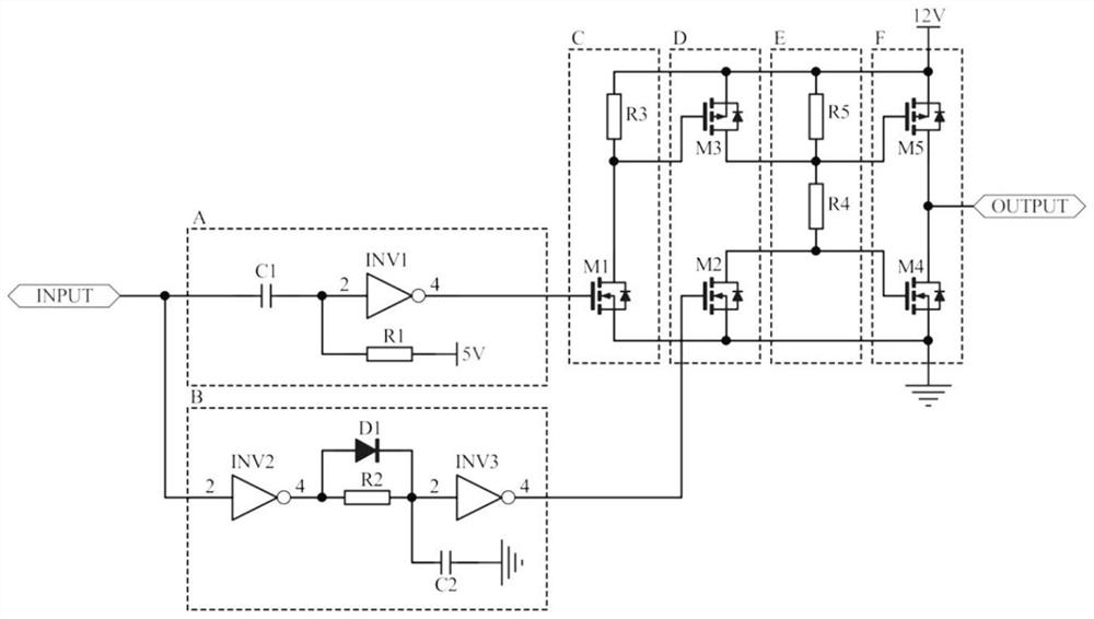
[0098] After the circuit is powered on, it enters the initial state or static state. At this time, the input terminal is in a low-level state, and the gates of the field-effect transistor M1 and the field-effect transistor M2 are both low-level, so the field-effect transistor M1, field-effect transistor M2 and The field effect transistor M3 is in the off state, which has no influence on the state of the subsequent module. The bias resistor R4 and the resistor R5 force the field effect transistor M4 to be turned on, the field effect transistor M5 is turned off, and the OUTPUT output is at a low level.

[0099] When the rising edge of the INPUT input pulse signal arrives, since the edge detection module A is a falling edge detection module, which can block the transmission of the rising edge signal, the state of the gate of the field effect transistor M1 does not change, and it still maintains a low level state. That is, the field effect transistor M3 is still in a state of high ...


PUM


Abstract

The invention discloses a MOS field effect transistor drive circuit and a control method, belonging to the technical field of drive circuits. The existing drive circuit built with discrete components cannot effectively ensure the same delay for the two edges of the input PWM signal, resulting in signal transmission distortion. A MOS field effect transistor drive circuit of the present invention is provided with an edge detection module A and a delay module B, which are used to divide two edges of an INPUT input pulse signal into two signal channels A and B for processing respectively. The edge detection module A is used to generate a pulse signal to an edge of the input pulse signal; the delay module B is used to delay the two edges of the input pulse signal respectively; the present invention sets the edge detection module A and delay module B, so that the delay of the rising edge of the input pulse signal can be adjusted and matched with the delay of the falling edge, which can effectively ensure that the delay of the two edges of the input pulse signal is the same, realize accurate transmission of the signal, and avoid signal Transmission distortion, especially suitable for high frequency driving occasions.

Description

technical field [0001] The invention relates to a MOS field effect transistor drive circuit and a control method, belonging to the technical field of drive circuits. Background technique [0002] Chinese patent (publication number: CN110798199A) discloses a MOS tube drive circuit, the MOS tube drive circuit is connected to the MOS tube, and the MOS tube drive circuit includes: a drive power supply, a level conversion module and a push-pull module; a drive power supply Connect with the level conversion module and the push-pull module respectively, provide the voltage to be converted for the level conversion module, and provide the working voltage for the push-pull module; the level conversion module converts the voltage to be converted provided by the driving power supply, and supplies The module outputs the gate voltage; the push-pull module receives the gate voltage, and combines the working voltage provided by the driving power supply to push-pull the gate of the MOS tube ...

Claims


Application Information

Patent Timeline
Patent Type & Authority Patents(China)
IPC IPC(8): H02M1/088H02M1/38H02M1/32
CPCH02M1/088H02M1/38H02M1/32
Inventor 林德桂来健李荣焕胡民秦陈长林
Owner HANGZHOU DONGCHENG ELECTRONICS
Why Eureka
Try Eureka