Crushing tooth assembly and crusher

A technology of crushing teeth and crushers, which is applied in the direction of grain processing, etc., can solve the problems of insufficient space for cutting motors and cable troughs, high maintenance costs for crushers, and inability to transport conveyors, etc., to solve the problem of power source, Save installation space, low manufacturing cost and low use cost

Pending Publication Date: 2021-06-04
SHANGHAI TIANDI MINING EQUIP TECH CO LTD +2
View PDF0 Cites 0 Cited by
  • Summary
  • Abstract
  • Description
  • Claims
  • Application Information

AI Technical Summary

Problems solved by technology

[0002] For the crusher used on the mining machine, due to the need to crush high-hardness rock blocks, the crushing teeth are often easily damaged
Most of the crusher drums in the existing structure are integral structures, and damage to the crushing teeth often leads to the scrapping of the whole drum, so the use and maintenance cost of the crusher is relatively high
[0003] In addition, in order to adapt to the mining of thin or high-grade thin ore seams, for example, rocker arms of high-power (high-torque) cutting systems are usually used on bauxite mining machines. The rocker arms have low height, compact structure, and high power density. The cutting motor installed in the casing occupies a large space in the front and rear directions, so that there is not enough space between the cutting motor and the cable trough to install a conventional crushing device
However, in the actual mining of mining machines, there are often a large number of high-hardness bauxite rocks. After entering the conveyor, these bauxite rocks need to pass under the position where the cutting motor of the rocker arm is located, but many of them are large rocks. Unable to pass through, the final accumulation will cause the conveyor to fail to convey, and it needs to be shut down for manual cleaning, which is time-consuming and laborious, and also affects production capacity

Method used


Image

  • Crushing tooth assembly and crusher
  • Crushing tooth assembly and crusher
  • Crushing tooth assembly and crusher

Examples


Embodiment Construction

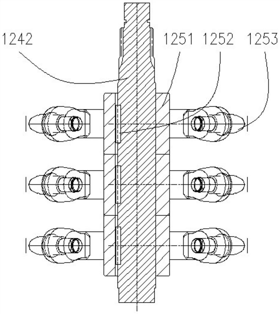
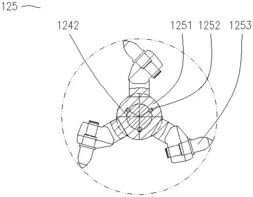
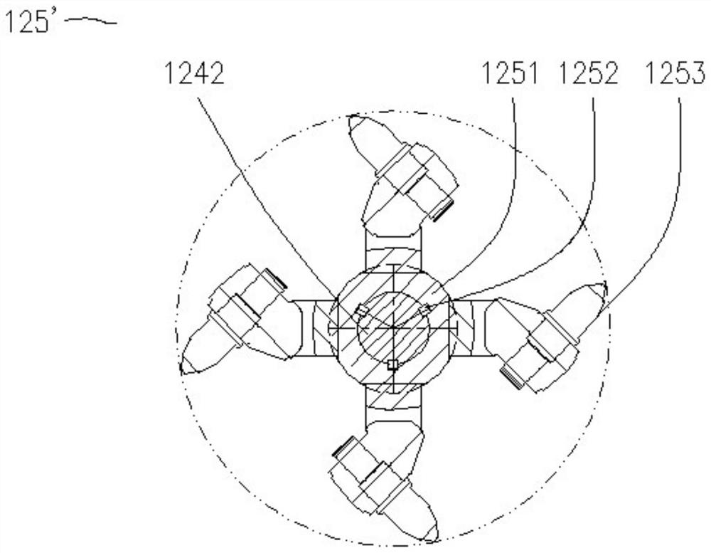
[0035] The invention discloses a crushing tooth assembly, such as Figure 1-7 As shown, it includes a connecting shaft 1242 and several crushing tooth groups 125, each of which includes a shaft sleeve 1251 and a plurality of crushing teeth 1253 fixed on the outer periphery of the shaft sleeve. The crushing tooth can be installed on the shaft sleeve through the crushing tooth seat. Each crushing tooth seat is equipped with a crushing tooth, and all the crushing teeth are installed in a clockwise or counterclockwise direction. The shaft sleeve and the connecting shaft of the group are connected by a plurality of flat keys 1252, and the multi-position flat keys are evenly distributed in the circumferential direction, the circumferential fixing is reliable, and the axial assembly and disassembly of the shaft sleeve is convenient. When a crushing tooth is damaged, it is only necessary to replace the crushing tooth and the shaft sleeve where it is located, and the maintenance is si...


PUM


Abstract

The invention discloses a crushing tooth assembly and a crusher. The crushing tooth assembly comprises a connecting shaft and a plurality of crushing tooth sets, each crushing tooth set comprises a shaft sleeve and a plurality of crushing teeth fixed to the periphery of the shaft sleeve, and the multiple crushing tooth sets are arranged side by side in a sleeving mode and fixed to the connecting shaft in the circumferential direction. The crusher comprises a mining machine rocker arm, a fixing base, a swinging arm and a crushing tooth assembly, wherein the fixing base is fixed to the rocker arm, a tubular structure extending front and back is arranged at one end of the swinging arm and hinged to the fixing base, the front end and the rear end of a rotating shaft are rotationally supported at the front end and the rear end of an inner cavity of the tubular structure respectively, the front end and the rear end of the connecting shaft are rotationally supported on a front arm frame and a rear arm frame at the other end of the swing arm respectively, and the front portion of the rotating shaft is in transmission connection with the front portion of the connecting shaft through a transmission system located in an inner cavity of the front arm frame. The crushing teeth can be partially replaced, so that the use cost can be reduced, and the crusher is compact in structure and can be used for an alumina mining machine for exploiting a thin ore bed.

Description

technical field [0001] The invention relates to a crushing tooth assembly for a crusher on a mining machine and a crusher using the crushing tooth assembly. Background technique [0002] For the crusher used on the mining machine, due to the need to break high-hardness rock blocks, the broken teeth are often easily damaged. Most of the crusher drums in the existing structure have an integral structure, and damage to the crushing teeth often leads to the scrapping of the whole drum, so the use and maintenance cost of the crusher is relatively high. [0003] In addition, in order to adapt to the mining of thin or high-grade thin ore seams, for example, rocker arms of high-power (high-torque) cutting systems are usually used on bauxite mining machines. The rocker arms have low height, compact structure, and high power density. The cutting motor arranged in the casing occupies a relatively large space in the front and rear directions, so that there is not enough space between t...

Claims


Application Information

Patent Timeline
IPC IPC(8): B02C18/10B02C18/24B02C18/16B02C23/04
CPCB02C18/10B02C18/16B02C18/24B02C23/04
Inventor 胡璟章立强周常飞宋相坤郭岱王振乾陈峤鹰宋振张斌董超胡滔顾恩洋丁海春刘凯朱信平胡俊王广张晓永吴振毅王兆胜李辉贾思然
Owner SHANGHAI TIANDI MINING EQUIP TECH CO LTD
Why Eureka
Try Eureka