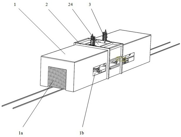
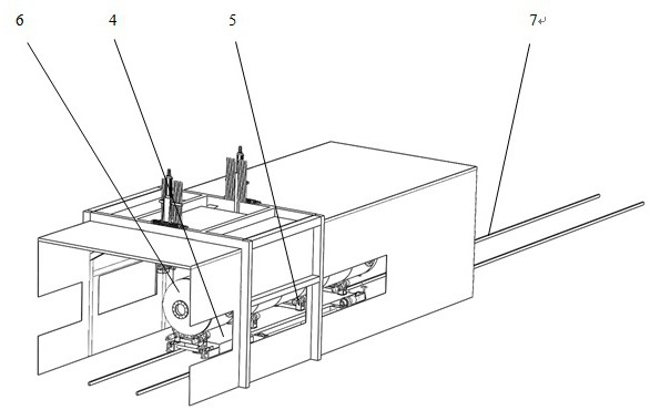
Large stainless steel container surface sand blasting equipment and automatic sand blasting production line
A surface sandblasting and stainless steel technology, which is applied in metal processing equipment, abrasive jetting machine tools, used abrasive processing devices, etc., can solve the problems of manual sandblasting labor intensity, low sandblasting efficiency, and harsh working environment
- Summary
- Abstract
- Description
- Claims
- Application Information
AI Technical Summary
Problems solved by technology
Method used
Image

Examples
Embodiment Construction
[0029] In order to better illustrate the purpose, technical solutions and advantages of the present invention, the present invention will be further described below in conjunction with specific embodiments. This invention may be embodied in many different forms and should not be construed as limited to the embodiments set forth herein. Rather, these embodiments are provided so that this disclosure will be thorough and complete and will fully convey the concept of the invention to those skilled in the art, and the present invention will only be defined by the appended claims.
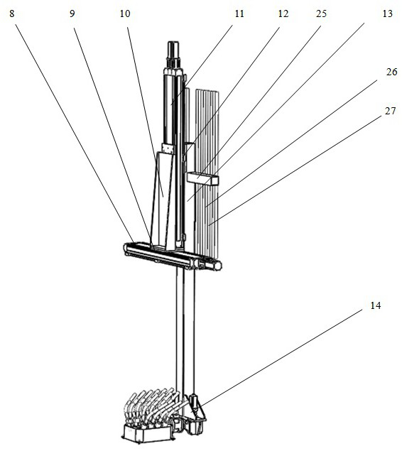
[0030] Such as Figure 3-4 As shown, the present invention provides a large-scale stainless steel container surface sandblasting equipment, including a device body 3, the device body 3 includes a lifting column 13 and a lifting column servo drive module, and the lifting column servo drive module drives the lifting column 13 horizontally and vertically move.
[0031] Preferably, the lifting column servo ...
PUM
 Abstract
Description
Claims
Application Information