[0046] The present invention will be described in detail below in conjunction with specific embodiments. The following examples will help those skilled in the art to further understand the present invention, but do not limit the present invention in any form. It should be noted that those skilled in the art can make several modifications and improvements without departing from the concept of the present invention. These all belong to the protection scope of the present invention.
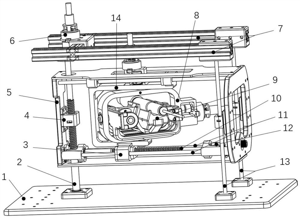
[0047] An embodiment of the present invention provides a frame-type multi-degree-of-freedom operating robot, which includes: an end effector, a two-degree-of-freedom position adjustment module, a two-degree-of-freedom attitude adjustment module, and an end-effector feeding module; wherein:
[0048] The two-degree-of-freedom attitude adjustment module is installed in the frame of the two-degree-of-freedom position adjustment module, and is used to realize the positioning of the two-degree-of-freedom attitude adjustment module in the vertical plane; the end effector feed module is installed in the two-degree-of-freedom attitude adjustment module In the framework of the end effector, it is used to adjust the pitch angle and yaw angle of the end effector feeding module; the end effector is installed on the end effector feeding module, and is used to realize the feeding movement in the direction of the end effector; Furthermore, the five degrees of freedom of the spatial position, pitch angle attitude and yaw angle attitude of the end effector are realized.
[0049] figure 1 A schematic structural diagram of a frame-type multi-degree-of-freedom manipulating robot provided for a preferred embodiment of the present invention.
[0050] like figure 1 As shown, the frame-type multi-degree-of-freedom manipulator provided in this preferred embodiment may include: an end effector and a transmission assembly connected to the end effector; wherein:
[0051] The end effector 904 is connected with the transmission assembly, and the end effector 904 is driven by the transmission assembly to realize multi-degree-of-freedom movement; the transmission assembly includes a two-degree-of-freedom position adjustment module, a two-degree-of-freedom attitude adjustment module 8 and an end-effector feed module 9; Among them, the two-degree-of-freedom position adjustment module can realize the positioning of the two-degree-of-freedom attitude adjustment module in the vertical plane, and the two-degree-of-freedom attitude adjustment module 8 can realize the adjustment of the pitch angle and the yaw angle of the end effector feed module 9. The actuator feeding module 9 can complete the feeding movement in the direction of the end effector 904; the robot can realize the five degrees of freedom of the spatial position of the end effector 904 and the attitude of pitch angle and yaw angle;
[0052] In the transmission assembly, there are auxiliary moving parts, reducers and actuators, etc. used to assist the transmission parts to move within a given range; among them:
[0053] Auxiliary moving parts include guide rods and moving frames; among them, the guiding rods can guide the movement of the transmission parts, and keep the overall moving parts stable to ensure the stability and reliability of the transmission; the moving frame can provide a carrying platform for the moving parts, and the frame The type design can provide the largest possible movement space for the moving parts and expand the working range;
[0054] The reducer is used as a transmission mechanism to improve the transmission power and ensure the stability and reliability of the transmission;
[0055] The actuator and the reducer are connected through flexible transmission components such as flexible shafts; the active mechanism such as the actuator is set separately from the transmission mechanism, and is connected with the reducer through flexible transmission components such as flexible shafts, which can reduce the weight of the movement mechanism to the greatest extent.
[0056] In other preferred embodiments of the present invention, the two-degree-of-freedom position adjustment module includes: a base plate, a vertical drive screw 2, a horizontal nut 3, a vertical nut 4, a height adjustment frame 5, a first reducer 6, Frame 7, horizontal drive screw mandrel 10, horizontal guide rod 11, second speed reducer 12, vertical guide rod 13, horizontal movement frame (14), first actuator and second actuator; Wherein,
[0057] One end of the vertical driving screw mandrel 2 is vertically installed on the base plate 1 through a bearing; the vertical nut 4 matched with it forms a helical pair with the vertical driving screw mandrel 2, and the rotation of the vertical driving screw mandrel 2 by driving can make The vertical nut 4 moves linearly in the direction of the vertical drive screw 2; the other end of the vertical drive screw 2 is connected to the output end of the first reducer 6 through a coupling, and the input end of the first reducer 6 passes through Flexible transmission materials such as flexible shafts are connected to the driving shaft of the first actuator; the first reducer 6 is installed on the frame 7 above the mechanism through bolts;
[0058] The height adjustment frame 5 is a rectangular frame member, and the vertical nut 4 is connected to the left frame of the height adjustment frame 5 by bolts, and the up and down movement of the vertical nut 4 can drive the height adjustment frame 5 to move up and down;
[0059] The horizontal driving screw 10 is mounted on the inside of the height adjustment frame 5 through bearings, one end of the horizontal driving screw 10 is connected with the left frame of the height adjustment frame 5 through a bearing, and the other end is connected with the right frame through a bearing; the horizontal nut 3 is connected with the horizontal drive The screw mandrel 10 forms a helical pair, and the horizontal nut 3 can be moved linearly in the direction of the horizontal drive screw mandrel 10 by driving the horizontal drive screw mandrel 10 to rotate; The output end is connected, and the input end of the second reducer 12 is connected with the driving shaft of the second actuator through a flexible transmission material such as a flexible shaft; the second reducer is installed on the right frame of the height adjustment frame 5 through bolts;
[0060] The horizontal moving frame 14 is a U-shaped frame, and is fixed on the horizontal nut 3, moves in the horizontal direction along with the horizontal nut 3;
[0061] On base base plate 1, be fixed with two vertically placed vertical guide rods 13, the other end of vertical guide rod 13 is fixed on the frame 7; The through holes on the top are matched; the vertical guide rod 13 can assist the vertical nut 4 to drive the height adjustment frame 5 to move in the vertical direction, and make the movement more stable, preventing the height adjustment frame 5 from being unevenly stressed and tilting;
[0062] Four horizontal guide rods 11 are arranged inside the height adjustment frame 5, and the two ends of the horizontal guide rods 11 are respectively fixed on the left and right frames of the height adjustment frame 5, and cooperate with four through holes of the horizontal adjustment frame 14 to guide the horizontal The moving frame 14 moves in the horizontal direction, and can help the horizontal moving frame to keep stable in motion.
[0063] In other preferred embodiments of the present invention, the vertical driving screw 2 and the horizontal driving screw 10 are arranged perpendicular to each other, and the vertical driving screw 2 is fixed on the bottom plate of the base, and the horizontal driving screw 10 is fixed on the height adjustment frame 5 on.
[0064] In other preferred embodiments of the present invention, two vertical guide rods 13 are respectively arranged on both sides of the height adjustment frame 5, and are parallel to the vertical driving screw 2; two of the four horizontal guide rods 11 are arranged On the upper side of the height adjustment frame 5, and cooperate with the upper through hole of the horizontal movement frame 14, the other two horizontal guide rods are arranged on the lower side of the height adjustment frame 5, and cooperate with the lower through hole of the horizontal movement frame 14.
[0065] In other preferred embodiments of the present invention, the two arms of the U-shaped horizontal movement frame 14 are provided with coaxial through holes for placing the bearings and the two-degree-of-freedom attitude adjustment module 8 .
[0066] In other preferred embodiments of the present invention, such as figure 2 As shown, the two-degree-of-freedom attitude adjustment module 8 includes a yaw angle adjustment frame 801, a pitch angle adjustment frame 802, a third reducer 803, a fourth reducer 804, a yaw angle rotation axis 805, a pitch angle rotation axis 806, The third actuator and the fourth actuator; wherein,
[0067] The yaw angle adjustment frame 801 is a rectangular frame slightly smaller than the horizontal movement frame 14. The upper and lower sides of the yaw angle adjustment frame 801 are provided with coaxial threaded holes, and the yaw angle rotation axis 805 is fixed at the yaw angle by threads. The adjustment frame 801 is connected to the coaxial through hole of the horizontal movement frame 14 through bearings; the left and right sides of the yaw angle adjustment frame 801 are provided with coaxial through holes;
[0068] The pitch angle adjustment frame 802 is a U-shaped frame, and coaxial threaded holes are arranged on its two arms, and the pitch angle rotation shaft 806 is connected with it by threads, and is connected with the yaw angle adjustment frame 801 through bearings;
[0069] One of the yaw angle rotation shafts 805 on the yaw angle adjustment frame 801 is connected to the output shaft of the third speed reducer 803 through a coupling, and the input end of the third speed reducer 803 is connected to the third speed reducer 803 through a flexible transmission material such as a flexible shaft. The driving shafts of the three actuators are connected; the third reducer 803 is installed on the upper arm of the horizontally moving frame 14 by bolts;
[0070] One of the pitch angle rotation shafts 806 on the pitch angle adjustment frame 802 is connected to the output shaft of the fourth reducer 804 through a coupling, and the input end of the fourth reducer 804 is connected to the fourth reducer through a flexible transmission material such as a flexible shaft. The drive shaft of the actuator is connected; the fourth speed reducer 804 is installed on the right frame of the yaw angle adjustment frame 801 by bolts.
[0071] In other preferred embodiments of the present invention, the axes of the yaw angle rotation axis 805 and the pitch angle rotation axis 806 are perpendicular to each other, and the horizontal movement frame 14, the yaw angle adjustment frame 801 and the pitch angle adjustment frame 802 are connected at the rotation axis. A U pair is formed below; the posture of the end effector 904 can be adjusted under the driving of the third actuator and the fourth actuator.
[0072] In other preferred embodiments of the present invention, such as image 3 As shown, the end effector feed module 9 includes: a feed nut 901, a feed drive screw 902, a bearing seat 903, a feed guide rod 905, an end effector clamp 906, a fifth speed reducer 907 and a fifth actuator Actuator;
[0073] The two ends of the feed driving screw 902 are respectively installed on two bearing blocks 903 through bearings, and the bearing block 903 is fixed on one of the arms of the pitch angle adjustment frame 802; one end of the feed driving screw 902 is connected by a coupling At the output end of the fifth reducer 907, the input end of the fifth reducer 907 is connected with the driving shaft of the fifth actuator through a flexible transmission material such as a flexible shaft; the fifth reducer 907 is installed on the bearing seat 903 by bolts On one arm; the feed nut 901 cooperates with the feed drive screw 902, and the feed nut 901 can be moved in the feed direction by the rotation of the feed drive screw 902;
[0074]The feed guide rod 905 is installed opposite to the feed drive screw 902 on the other arm of the pitch angle adjustment frame 802, and is used to assist the movement of the end effector 904 in the feed direction and balance the movement of the end effector 904;
[0075] One side of the end effector fixture 906 is fixed on the feed nut 901 by bolts, and the other side is provided with a through hole, which is matched with the feed guide rod 905; the end effector part 904 is fixed on the end effector fixture 906, and the end effector The component 904 moves with the end effector grip 906;
[0076] In other preferred embodiments of the present invention, the feed guide rod 905 is parallel to the feed drive screw 902 .
[0077] In the frame-type multi-degree-of-freedom operating robot provided by the above-mentioned embodiments of the present invention, the vertical driving screw rod and the horizontal driving screw rod in the two-degree-of-freedom position adjustment module are arranged perpendicular to each other; The navigation angle adjustment frame and the pitch angle adjustment frame form a U pair, and the two rotation axes connected to it are arranged perpendicular to each other; through the two-degree-of-freedom position adjustment module, the two-degree-of-freedom attitude adjustment module and the end-effector feed module, the end-effector can be driven. The execution part realizes multi-degree-of-freedom movement. The frame-type multi-degree-of-freedom operating robot provided by the above-mentioned embodiments of the present invention has the advantages of stable operation, high rigidity, high strength, simple structure, light weight and low control cost through the control of five peripheral actuators.
[0078] In describing the present invention, it is to be understood that the terms "upper", "lower", "front", "rear", "left", "right", "vertical", "horizontal", "top", The orientation or positional relationship indicated by "bottom", "inner", "outer", etc. is based on the orientation or positional relationship shown in the drawings, and is only for the convenience of describing the simplified description of the present invention, rather than indicating or implying the referred device Or that an element must have a particular orientation, be constructed and operate in a particular orientation, and thus should not be construed as limiting the invention.
[0079] Specific embodiments of the present invention have been described above. It should be understood that the present invention is not limited to the specific embodiments described above, and those skilled in the art may make various changes or modifications within the scope of the claims, which do not affect the essence of the present invention.