


Quick Research
Generate reliable direction feasibility study reports for your R&D in just a few steps.

Technical Q&A
Discover and master advanced knowledge NOW. Basics, ideas, possibilities, all at once.

Find Solutions
As an expert in R&D theories, this can generate solutions to your technical problems instantly.

Evaluate Feasibility
Analyze your overall solution with one click, know your potential R&D risks in advance.

Monitor Landscape
Get weekly tech updates, stay abreast of the latest tech innovations and key insights.
Garbage can capable of improving utilization rate of garbage bag
A technology of utilization rate and garbage can, applied in the field of garbage cans, can solve the problem that garbage bags cannot be fully utilized, and achieve the effect of reducing the probability of dust contamination, reducing noise, and facilitating operation.
- Summary
- Abstract
- Description
- Claims
- Application Information
AI Technical Summary
Problems solved by technology
Method used
Image

Examples
Embodiment 1
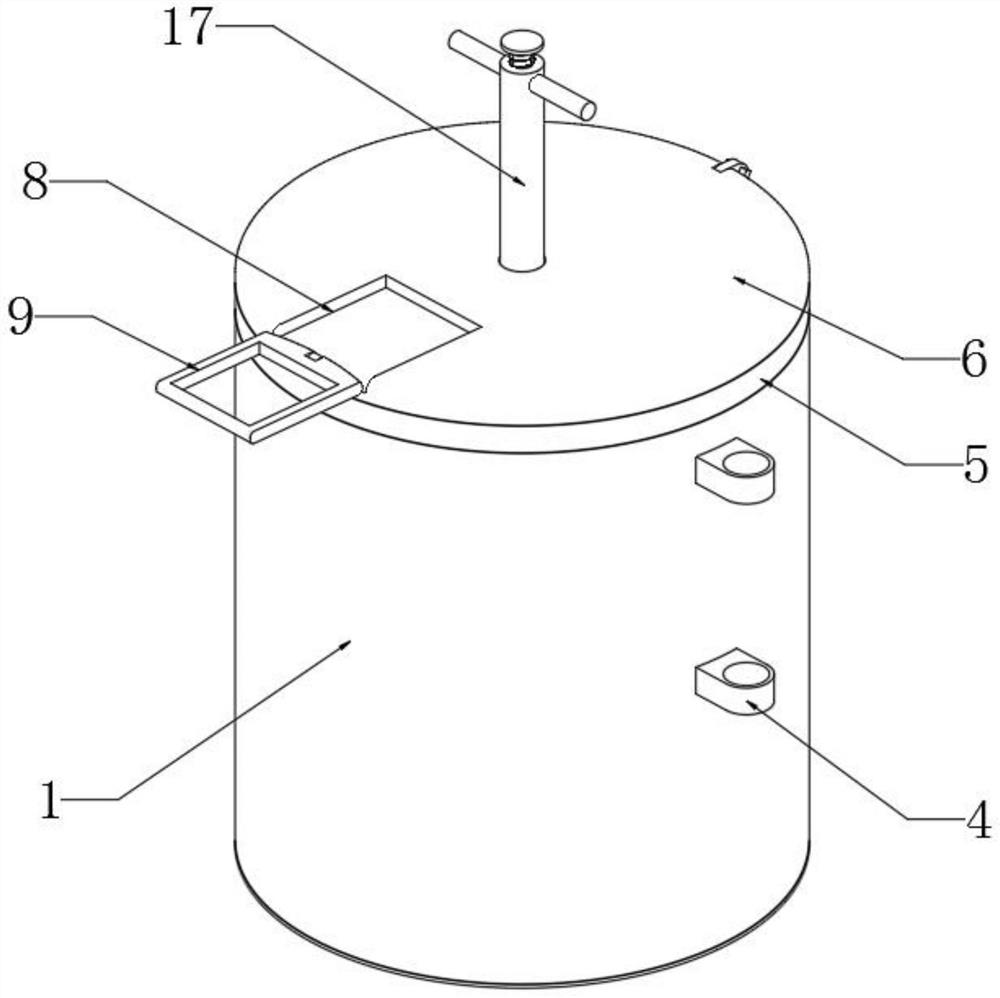
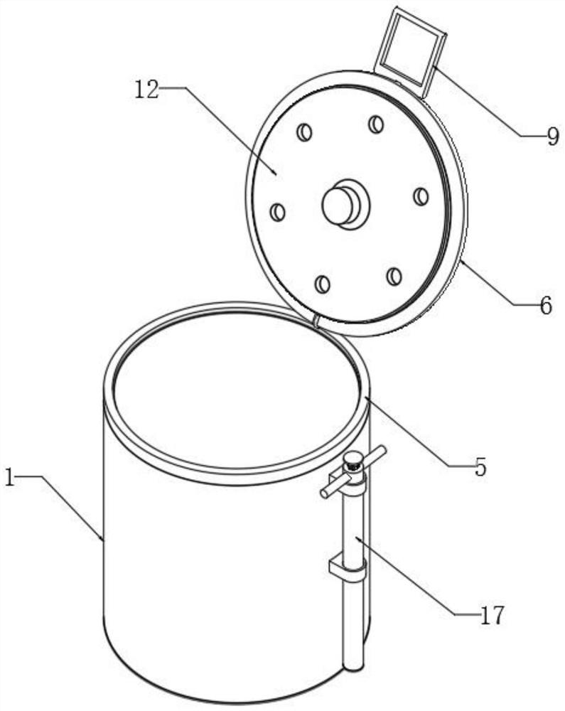
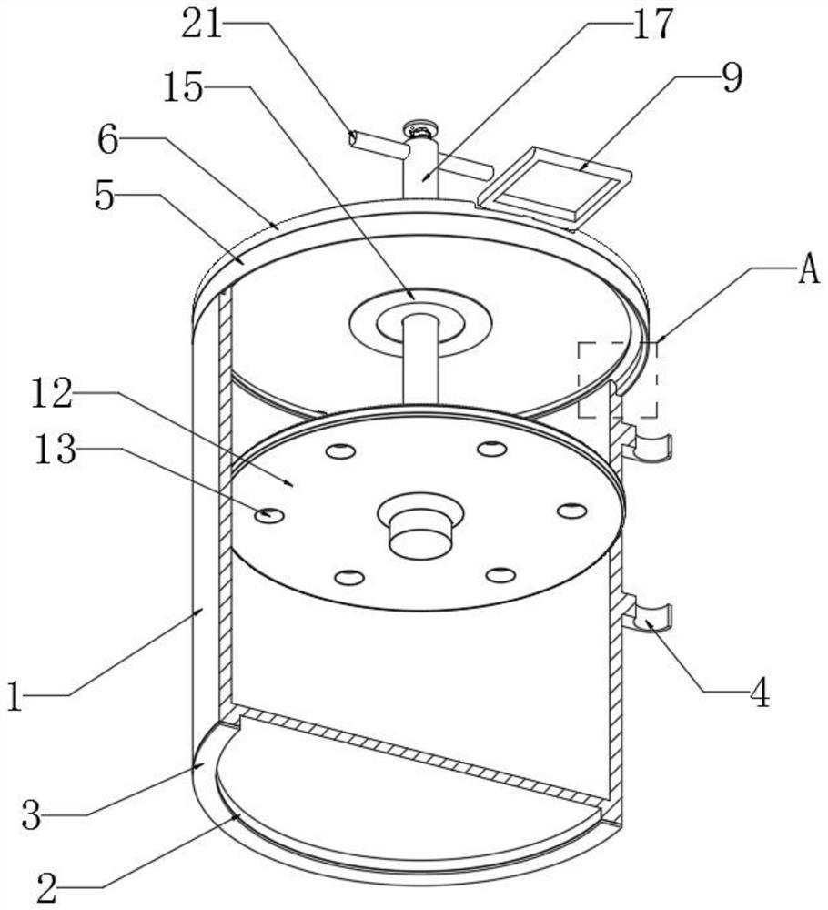
[0048] The operation process of this device for compressing garbage is as follows: press down the round tube 17 through the handlebar 21, push down the pressing plate 12 through the round tube 17, so that the pressing plate 12 overcomes the suction force of the first magnetic ring 14 and the second magnetic ring 15 to disengage. Cover 6, and continue to compress the garbage downward. After the compression is completed, lift the round tube 17 until the pressure plate 12 is re-adsorbed and fixed under the end cover 6 by the first magnetic ring 14 and the second magnetic ring 15, and continue to lift the round tube 17, so that the round tube 17 overcomes the suction force of the third magnetic ring 18 and the fourth magnetic ring 19 to break away from the pressure plate 12, and the end cover 6 can be opened to continue using the device;
[0049] The bagging and cleaning process of the device is as follows: remove the parts such as the end cap 6 connected with the collar 5 from the...
Embodiment 2
[0051] The difference between this device and the above-mentioned Embodiment 1 is that, as Figure 8 As shown, an inner cylinder 25 can be added inside the device, and the bottom end of the inner cylinder 25 is connected with a loading tray 24 through a damping rod 26, and the garbage bag is sleeved in the inner cylinder 25. The damping rod 26 adopts existing equipment and has a certain The shrinkage makes the loading tray 24 at a high position when it is empty. When there is more garbage in the garbage bag, the damping rod 26 stretches out under the action of garbage gravity, so that the loading tray 24 descends and releases more garbage in the garbage can. Space, thereby increasing the volume occupancy rate of garbage bags in the garbage can.
PUM
 Abstract
Description
Claims
Application Information
 - R&D Engineer
- R&D Manager
- IP Professional
- Industry Leading Data Capabilities
- Powerful AI technology
- Patent DNA Extraction
Browse by: Latest US Patents, China's latest patents, Technical Efficacy Thesaurus, Application Domain, Technology Topic, Popular Technical Reports.
© 2024 PatSnap. All rights reserved.Legal|Privacy policy|Modern Slavery Act Transparency Statement|Sitemap|About US| Contact US: help@patsnap.com