Electrorheological elastomer vibration isolator in compression-shear mixed mode

An electro-rheological elastomer, mixed-mode technology, used in shock absorbers, springs/shock absorbers, springs, etc., can solve the problem of difficulty in fully exerting the variable stiffness and damping characteristics of electro-rheological elastomers and the material properties of electro-rheological elastomers The problems of low utilization rate and small vertical displacement of electrorheological elastomers can improve the utilization rate of materials, ensure the bearing capacity, and increase the vertical displacement.

Pending Publication Date: 2021-06-04
TAIYUAN UNIV OF TECH
View PDF9 Cites 0 Cited by
  • Summary
  • Abstract
  • Description
  • Claims
  • Application Information

AI Technical Summary

Problems solved by technology

[0004] In recent research, scholars have proposed some intelligent material vibration isolation device designs, such as an electrorheological elastomer intelligent vibration isolation support with application publication number CN103806569A, which uses electrorheological elastomer as a variable stiffness vibration isolation material for development For the semi-active shock absorber, in order to ensure a certain vertical bearing capacity, the electrorheological elastomer in this structure is installed horizontally, the vertical displacement of the electrorheological elastomer is small, and the lateral displacement is large. , lower vibration) electrorheological elastomers only produce tension and compression deformation (the tension and compression deformation corresponds to the vertical displacement), there is no shear deformation (the shear deformation corresponds to the lateral displacement), it is difficult to give full play to the electrorheological elastomer under the control of the external field Variable stiffness and damping characteristics, low utilization of the material properties of electrorheological elastomers

Method used


Image

  • Electrorheological elastomer vibration isolator in compression-shear mixed mode
  • Electrorheological elastomer vibration isolator in compression-shear mixed mode
  • Electrorheological elastomer vibration isolator in compression-shear mixed mode

Examples


Embodiment Construction

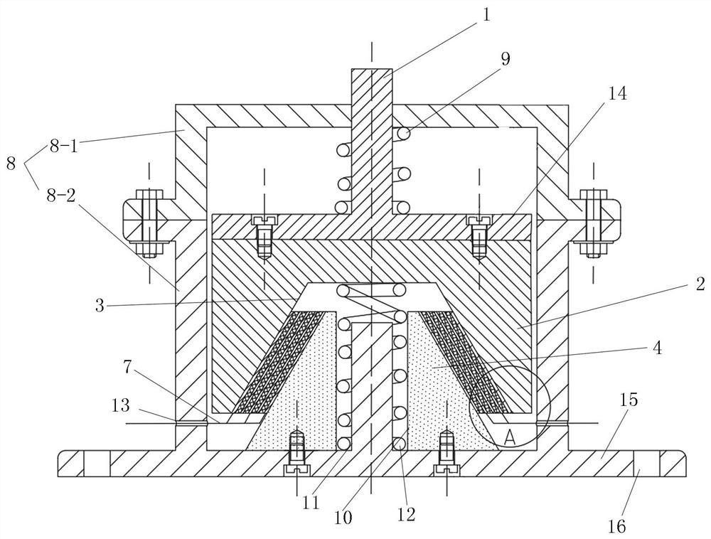
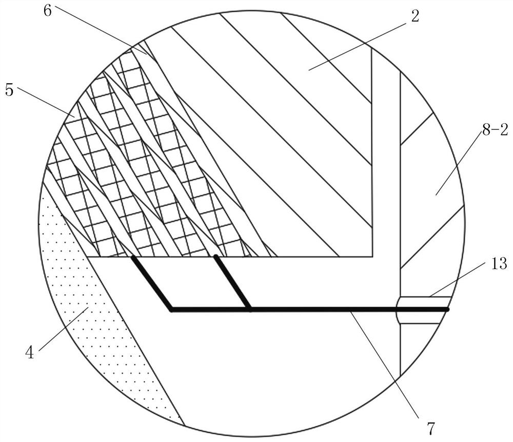
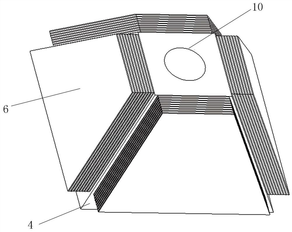
[0013] A pressure-shear mixed mode electrorheological elastomer vibration isolator, including a housing 8, a gland 2 located in the housing 8, and a support platform 4 with a tapered surface, the bottom surface of the support platform 4 is located at the bottom of the housing 8 In the center, the gland 2 is located above the support platform 4, the bottom surface of the gland 2 is provided with a groove 3 that is compatible with the support platform 4, and a multi-layer is fixed between the side wall of the groove 3 and the side wall of the support platform 4. Electrode pieces, electrorheological elastomers 5 are fixed between adjacent two layers of electrode pieces, the electrode pieces close to the groove 3 are fixed on the side wall of the groove 3, and the electrode pieces close to the support platform 4 are fixed on the side of the support platform 4 wall, so that the electrorheological elastomer 5 located between the groove 3 of the gland 2 and the support table 4 realize...


PUM


Abstract

The invention relates to an electrorheological elastomer vibration isolator, in particular to the electrorheological elastomer vibration isolator in a compression-shear mixed mode. The invention provides a novel electrorheological elastomer vibration isolator in order to solve the problem that an existing intelligent vibration isolation support of an electrorheological elastomer is low in utilization rate of material performance of the electrorheological elastomer, the novel electrorheological elastomer vibration isolator comprises a shell, a gland located in the shell and a supporting table with a conical surface, the bottom face of the supporting table is located in the center of the bottom of the shell, the gland is located above the supporting table, a groove matched with the supporting table is formed in the bottom face of the gland, multiple layers of electrode plates are fixedly arranged between the side wall of the groove and the side wall of the supporting table, the electrorheological elastomer is fixedly arranged between every two adjacent electrode plates, so that the electrorheological elastomer located between the groove of the gland and the supporting table achieves compression-shear composite deformation, and the top of the gland is fixedly connected with a vibration isolation compression rod extending out of the top of the shell, so that the material utilization rate of the electrorheological elastomer is improved.

Description

technical field [0001] The invention relates to an intelligent material vibration isolator, in particular to an electrorheological elastomer vibration isolator, in particular to an electrorheological elastomer vibration isolator in a compression-shear mixed mode. Background technique [0002] Vibration phenomena exist in various mechanical fields such as aerospace, military, automobile, and chemical industry. Vibration phenomena not only reduce production efficiency, but also shorten the service life of machines. Therefore, the research on vibration control is very important. At present, traditional passive vibration isolators still occupy the main market, but their stiffness and damping cannot be adjusted, and the vibration isolation effect is not ideal when the vibration frequency or vibration amplitude changes. [0003] In recent years, due to the rapid development of smart materials, vibration isolation technology based on smart materials has attracted the attention of r...

Claims


Application Information

Patent Timeline
Patent Type & Authority Applications(China)
IPC IPC(8): F16F15/03F16F15/067
CPCF16F15/03F16F15/067F16F2224/043
Inventor 钮晨光任俊锜武兵付骏宇牛蔺楷熊晓燕李国彦李聪明
Owner TAIYUAN UNIV OF TECH
Why Eureka
Try Eureka