
Intelligent energy-saving and emission-reducing system of drying furnace

A technology of energy saving, emission reduction, and drying furnace, which is applied in the field of multi-painting system, can solve the problems of slow natural drying speed, increase of voc concentration, prolongation of production process, etc., and achieve the effect of increasing drying speed, avoiding porosity problems, and reducing energy consumption

Active Publication Date: 2021-06-04
DESIGN INST NO 9 MINISTRY OF MECHINE BUILDING
View PDF26 Cites 2 Cited by
  • Summary
  • Abstract
  • Description
  • Claims
  • Application Information

AI Technical Summary

Problems solved by technology

[0002]The spray booth is the place where various parts are painted, and due to the characteristics of the paint itself, when it is sprayed on the outer surface of the device, there will be natural flow At the same time, the natural drying speed is slow, which greatly prolongs the production process of the entire device, and then dissolves and uses the paint itself through an organic solvent, and then makes the organic solvent volatilize naturally after the painting is finished, thus making the voc concentration in the spray booth Greatly improved, it will cause damage to the operators. At the same time, when the air in the paint square is directly discharged into the atmosphere, it will be photolyzed and combined under natural light to form various organic pollutants, and then destroy the environment. For this reason, we propose a Drying furnace intelligent energy saving and emission reduction system

Method used


Image

  • Intelligent energy-saving and emission-reducing system of drying furnace
  • Intelligent energy-saving and emission-reducing system of drying furnace
  • Intelligent energy-saving and emission-reducing system of drying furnace

Examples


Embodiment Construction

[0026] The following will clearly and completely describe the technical solutions in the embodiments of the present invention with reference to the accompanying drawings in the embodiments of the present invention. Obviously, the described embodiments are only some, not all, embodiments of the present invention. Based on the embodiments of the present invention, all other embodiments obtained by persons of ordinary skill in the art without making creative efforts belong to the protection scope of the present invention.

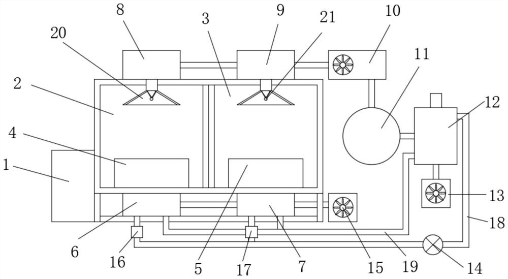
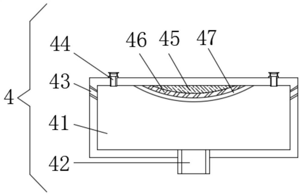
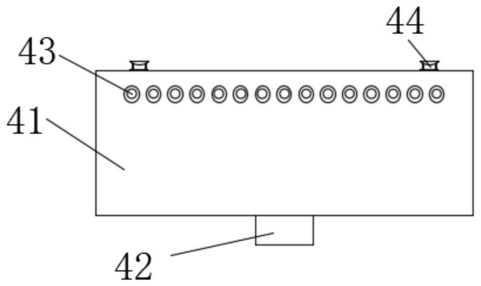
[0027] see Figure 1-8 , the present invention provides a technical solution: an intelligent energy saving and emission reduction system for a drying furnace, including a main controller 1, a flash drying chamber 2, a constant temperature chamber 3, a first fresh air fan 15, a concentration runner 11 and a pyrolysis furnace 12. The flash drying chamber 2 and the constant temperature chamber 3 are fixedly installed side by side, the main controller 1 is fixedly...


PUM


Abstract

The invention discloses an intelligent energy-saving and emission-reducing system of a drying furnace. The intelligent energy-saving and emission-reducing system comprises a main controller, a flash drying chamber, a constant temperature chamber, a first fresh air machine, a concentration runner device and a pyrolyzing furnace, wherein the flash drying chamber and the constant temperature chamber are fixedly arranged side by side, and the main controller is fixedly arranged on the outer wall of the left side of the flash drying chamber; paint on the surface of a device can be subjected to flash drying through the flash drying chamber, so that a curing film layer is formed on the surface of the paint, and the phenomenon of leveling is avoided; the paint between the surface of the device and the curing film layer can be evaporated to be dry at a constant speed through the constant temperature chamber at a constant temperature, so that the drying speed is increased, and meanwhile, the problems of paint brick cracking and air holes caused by too fast drying are avoided; air containing organic solvent gas is concentrated through the concentration runner device and then is guided into the pyrolyzing furnace, so that the organic solvent gas is subjected to oxidation pyrolysis, and the pollution is reduced; and through a heat conduction pipe and a cold return pipe, heat generated when the pyrolyzing furnace is used for carrying out oxidation pyrolysis on the organic solvent gas is recycled, so that the energy consumption is reduced.

Description

technical field [0001] The invention relates to the technical field of multiple paint spraying systems, and the specific field is an intelligent energy-saving and emission-reducing system for a drying furnace. Background technique [0002] The paint spraying room is a place where various parts are painted, and due to the characteristics of the paint itself, when it is sprayed on the outer surface of the device, it will have a natural leveling, and at the same time the natural drying speed is slow, which in turn makes the production of the entire device The process is greatly extended, and then the paint itself is dissolved and used by organic solvents, and then the organic solvents are naturally volatilized after the painting is finished, which greatly increases the concentration of voc in the spray booth, causing damage to the operators, and at the same time, the air in the paint booth When directly discharged into the atmosphere, photolysis and compounding are carried out ...

Claims


Application Information

Patent Timeline
IPC IPC(8): F26B9/06F26B23/10F26B21/00F26B23/02F26B25/00F26B25/10F23G5/027F23G5/46
CPCF26B9/06F26B23/10F26B21/001F26B21/002F26B21/004F26B23/022F26B25/006F26B25/10F26B25/00F23G5/027F23G5/46
Inventor 孔小明陈建李伟
Owner DESIGN INST NO 9 MINISTRY OF MECHINE BUILDING
Learn More