Antenna structure and antenna array

An antenna structure and antenna main body technology, which is applied to antenna arrays, individually powered antenna arrays, and the connection of antenna grounding switch structures, etc., can solve the problem of unfavorable overall wireless performance stability, high power consumption and heat generation, affecting user experience and products. Comprehensive competitiveness and other issues to achieve the effect of improving data transmission speed, good antenna gain, good user wireless experience and product competitiveness

Active Publication Date: 2021-06-04
ETHETA COMM TECH SHENZHEN CO LTD
View PDF23 Cites 0 Cited by
  • Summary
  • Abstract
  • Description
  • Claims
  • Application Information

AI Technical Summary

Problems solved by technology

The millimeter-wave frequency band has multiple different frequency bands, so broadband or multi-frequency millimeter-wave antennas are the mainstream demand, and the existing broadband millimeter-wave antennas generally have a multi-port structure (that is, more than one port

Method used


Image

  • Antenna structure and antenna array
  • Antenna structure and antenna array
  • Antenna structure and antenna array

Examples


Embodiment 1

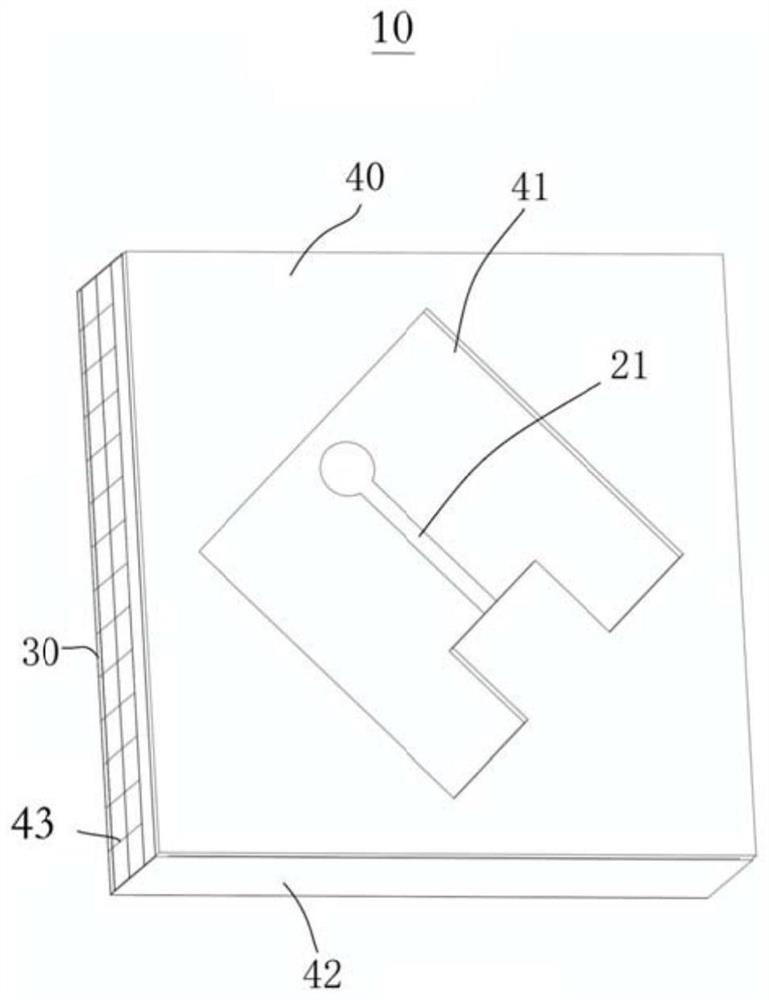
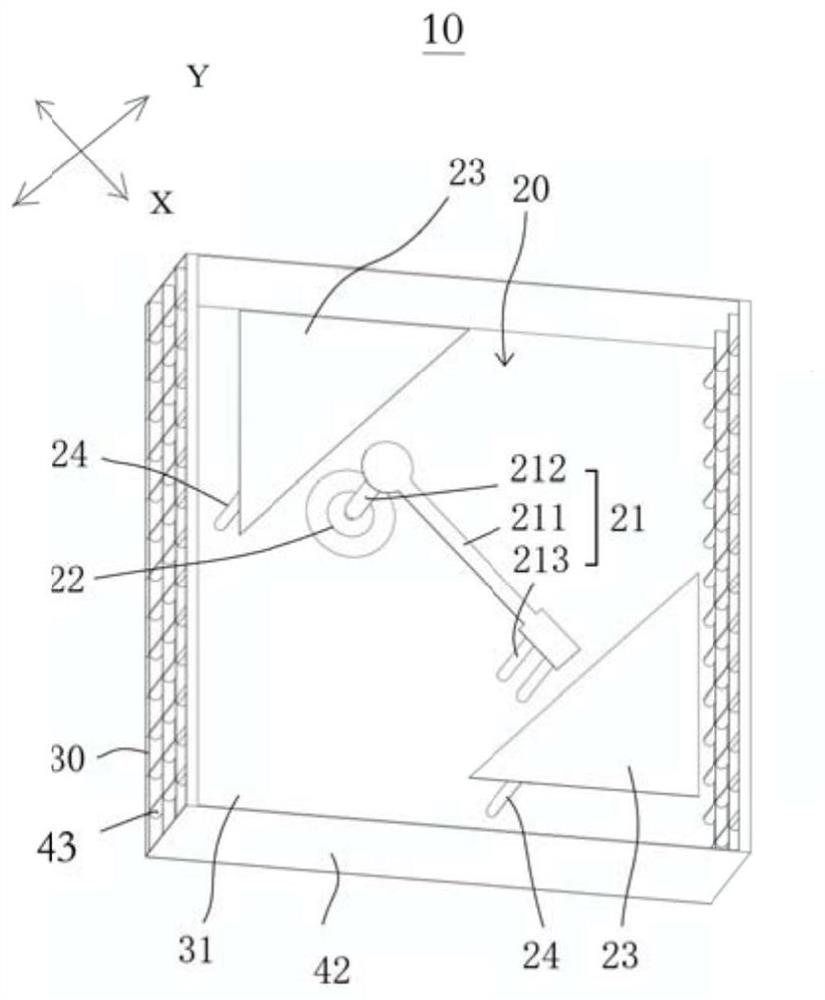
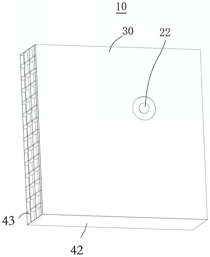
[0065] see figure 1 , figure 2 and image 3 , figure 1 is a perspective view of the antenna structure 10 provided in Embodiment 1 of the present application, figure 2 yes figure 1 The perspective view of the shown antenna structure after hiding the filling medium, image 3 yes figure 2 Another perspective view of the shown antenna structure with the filling medium hidden. The antenna structure 10 includes a first antenna component 20 , a carrier 30 , and a filling medium 40 . The first antenna component 20 is disposed on the carrier 30 , and the filling medium 40 is disposed on the carrier 30 and covers at least part of the first antenna component 20 .

[0066]The first antenna assembly 20 includes a first three-dimensional antenna 21 with one end grounded or connected to a reference potential, a single antenna port 22 connected to the other end of the first three-dimensional antenna 21 and a first three-dimensional antenna adjacent to the first three-dimensional ant...

Embodiment 2

[0083] see Figure 5 , Figure 5It is a perspective view of the antenna structure 10 provided in Embodiment 2 of the present application after the filling medium is hidden. The antenna structure 10 in the second embodiment is basically the same as the antenna structure 10 in the first embodiment, that is to say, the description of the antenna structure 10 in the first embodiment above can basically also be applied to the antenna structure 10 in the second embodiment, as follows The difference between the antenna structure 10 in the second embodiment and the antenna structure 10 in the first embodiment will be mainly described.

[0084] In the second embodiment, the antenna main body 211 includes a first connection part 2111 connected to the feeding part 212, a second connection part 2112 connected to the bent part 213, and a second connection part 2112 connected to the first connection part 2111 and the second connection part. The body portion 2113 between the portions 2112....

Embodiment 3

[0086] see Image 6 , Image 6 It is a perspective view of the antenna structure 10 provided in Embodiment 3 of the present application after the filling medium is hidden. The antenna structure 10 in the third embodiment is basically the same as the antenna structure 10 in the first embodiment, that is to say, the description of the antenna structure 10 in the first embodiment can basically be applied to the antenna structure 10 in the third embodiment, as follows The difference between the antenna structure 10 in the third embodiment and the antenna structure 10 in the first embodiment will be mainly described.

[0087] In the third embodiment, the first three-dimensional antenna 21 has a bent portion 213 , and the bent portion 213 can be connected between the antenna main body 21 and the reference ground layer 31 . It can be understood that one bent portion 213 is beneficial to reduce manufacturing complexity.


PUM


Abstract

The embodiment of the invention provides an antenna structure and an antenna array. The antenna structure comprises a first antenna assembly, and the first antenna assembly comprises a first three-dimensional antenna with one end grounded or connected with a reference potential, a single antenna port connected with the other end of the first three-dimensional antenna and a first parasitic structure arranged adjacent to the first three-dimensional antenna. In the antenna structure, the first three-dimensional antenna is only connected with a single antenna port, so that the number of ports required by the antenna can be reduced, that is, power consumption is reduced from the antenna dimension, heat is reduced, and stable overall antenna performance is maintained; meanwhile, a first parasitic structure is arranged adjacent to the first three-dimensional antenna. Therefore, the first antenna assembly can cover multi-frequency and broadband wavebands, such as the multi-frequency and broadband 5G millimeter wavebands, so that the user experience and the comprehensive competitiveness of the product can be remarkably improved.

Description

technical field [0001] The present invention relates to the technical field of antennas, in particular to an antenna structure and an antenna array. Background technique [0002] Now we have entered the era of 5G (fifth generation mobile communication), and 5G communication is divided into millimeter wave frequency band and non-millimeter wave frequency band. The millimeter-wave frequency band has multiple different frequency bands, so broadband or multi-frequency millimeter-wave antennas are the mainstream demand, and the existing broadband millimeter-wave antennas generally have a multi-port structure (that is, more than one port), so their power consumption and heat generation Both are relatively high, so it is unfavorable to the power consumption of the overall system and the stability of the overall wireless performance, thereby affecting the user experience and the overall competitiveness of the product. Contents of the invention [0003] Therefore, it is necessary ...

Claims


Application Information

Patent Timeline
IPC IPC(8): H01Q1/36H01Q1/50H01Q21/00
CPCH01Q1/36H01Q1/50H01Q21/00H01Q1/40H01Q1/526H01Q9/42H01Q21/08H01Q21/24H01Q5/385H01Q21/0006
Inventor 黄奂衢高大宋漆知行林虹周彦超
Owner ETHETA COMM TECH SHENZHEN CO LTD
Why Eureka
Try Eureka