Laminated patch antenna based on radiation regulation and control and communication equipment
A patch antenna and patch technology, applied in antennas, resonant antennas, electrical short antennas, etc., can solve problems such as low energy efficiency, improve overall energy efficiency, high energy utilization efficiency, and realize the effect of simultaneous transmission of energy and information
- Summary
- Abstract
- Description
- Claims
- Application Information
AI Technical Summary
Problems solved by technology
Method used
Image

Examples
Embodiment 1
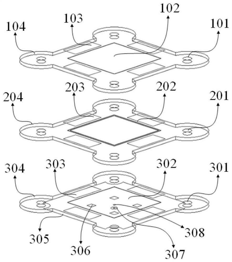
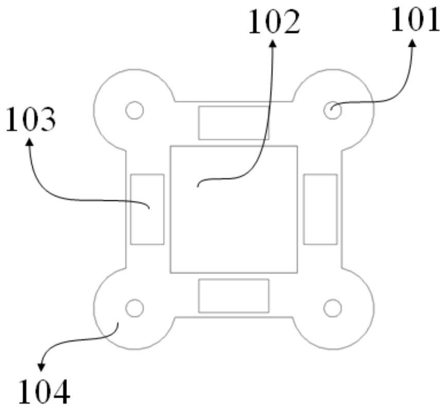
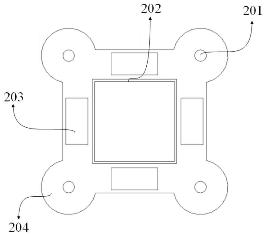
[0036] Such as figure 1 As shown, a stacked patch antenna based on radiation control, including stacked three-layer dielectric substrate, parasitic square patch unit, parasitic ring patch unit, main radiation patch unit, square symmetrical parasitic unit, defect ground plane and feed probes. The three dielectric substrates are respectively the first dielectric substrate 104 , the second dielectric substrate 204 and the third dielectric substrate 304 . The first dielectric substrate 104 , the second dielectric substrate 204 and the third dielectric substrate 304 all use low-loss dielectric plate Arlon AD255C, with a relative permittivity of 2.55 and a tangent loss of 0.0014. In order to maintain better radiation performance and mechanical reliability of the antenna, the thickness of the three-layer dielectric substrate in this embodiment is 3mil. At the same time, in order to be easy to assemble, each layer of dielectric substrates has reserved corner-cut ring columns for ins...
Embodiment 2
[0055] A communication device, comprising the radiation regulation-based stacked patch antenna described in Embodiment 1, comprising N stacked dielectric substrates, where N is greater than 2, and the first three dielectric substrates are the first dielectric substrate, the second dielectric substrate, respectively. Two dielectric substrates and a third dielectric substrate, one side of the first dielectric substrate is provided with a parasitic square patch unit, one side of the second dielectric substrate is provided with a parasitic annular patch unit, and one side of the third dielectric substrate is provided with a main radiation The patch unit has a defect structure on the other side, and square symmetrical parasitic units are arranged on one side of the first three dielectric substrates, which are respectively located around the parasitic square patch unit, the parasitic ring patch unit and the main radiation patch unit. The feeding structure for feeding the main radiati...
Embodiment 3
[0057] A multilayer patch antenna based on radiation regulation, which is different from Embodiment 1 in that it includes four dielectric substrates stacked, which are respectively a first dielectric substrate, a second dielectric substrate, a third dielectric substrate and a fourth dielectric substrate , the setting of the first three layers of dielectric substrates is the same as that of Embodiment 1, the fourth dielectric substrate is provided with parasitic square patch units, and symmetrical square symmetrical parasitic units are arranged around the parasitic square patch units, that is to say, the setting of the fourth dielectric substrate It is the same as the first dielectric substrate, and the distance between the fourth dielectric substrate and the first dielectric substrate is a quarter of the working wavelength. The working wavelength refers to the free space wavelength, and this design is a 5.8GHz free space wavelength.
PUM
| Property | Measurement | Unit |
|---|---|---|
| Radius | aaaaa | aaaaa |
Abstract
Description
Claims
Application Information
 - R&D
- Intellectual Property
- Life Sciences
- Materials
- Tech Scout
- Unparalleled Data Quality
- Higher Quality Content
- 60% Fewer Hallucinations
Browse by: Latest US Patents, China's latest patents, Technical Efficacy Thesaurus, Application Domain, Technology Topic, Popular Technical Reports.
© 2025 PatSnap. All rights reserved.Legal|Privacy policy|Modern Slavery Act Transparency Statement|Sitemap|About US| Contact US: help@patsnap.com