Supercharge Your Innovation With Domain-Expert AI Agents!

Terminal air conditioning system for multiple working conditions, control method and control device

An air-conditioning system and control method technology, applied in the direction of air-conditioning systems, applications, heating methods, etc., can solve problems such as terminal air-conditioning, large air volume in the input room, and large air duct resistance, etc., so as to improve human comfort and comprehensive energy efficiency The effect of improving and reducing power consumption

Pending Publication Date: 2022-03-25
GREE ELECTRIC APPLIANCES INC OF ZHUHAI
View PDF6 Cites 0 Cited by
  • Summary
  • Abstract
  • Description
  • Claims
  • Application Information

AI Technical Summary

Problems solved by technology

[0003] At present, the conventional air duct system of HVAC on the market is designed as one air supply duct and one return air duct. This type of air duct is designed according to the hotter working conditions in summer, without considering the need for air conditioners in the transition season and at the end of winter. The working condition of cooling but still needing air supply leads to large air passage resistance in the transition season and winter, large air volume input into the room, high energy consumption and uncomfortable situations; therefore, the purpose of the present invention is to provide a multi-working condition Use the terminal air-conditioning system, control method and control device to solve the deficiencies in the prior art

Method used


Image

  • Terminal air conditioning system for multiple working conditions, control method and control device
  • Terminal air conditioning system for multiple working conditions, control method and control device
  • Terminal air conditioning system for multiple working conditions, control method and control device

Examples


Embodiment 1

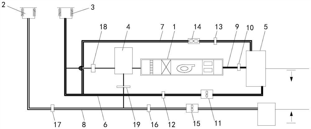
[0034] according to figure 1 As shown, this embodiment proposes a terminal air-conditioning system for multi-working conditions, including a combined air-conditioning unit body 1, an exhaust shaft 2, an air intake shaft 3, a fresh air duct 6, a winter air duct 7 and a return exhaust duct 8 , the system air duct of the combined air conditioning unit body 1 is provided with a fresh air duct 6 and a winter air duct 7, the winter air duct 7 is connected to the fresh air duct 6, and the fresh air duct 6 is connected to the air inlet shaft 3 , the return exhaust duct 8 is connected to the exhaust shaft 2 .

[0035] The fresh air duct 6 is provided with a fresh air blower 11 and a fresh air supply valve 12 , and the winter air duct 7 is provided with a winter air supply valve 13 and a winter fan 14 .

[0036] The combined air-conditioning unit body 1 is connected with a first air mixing chamber 4 and a second air mixing chamber 5, and the first air mixing chamber 4 is respectively c...

Embodiment 2

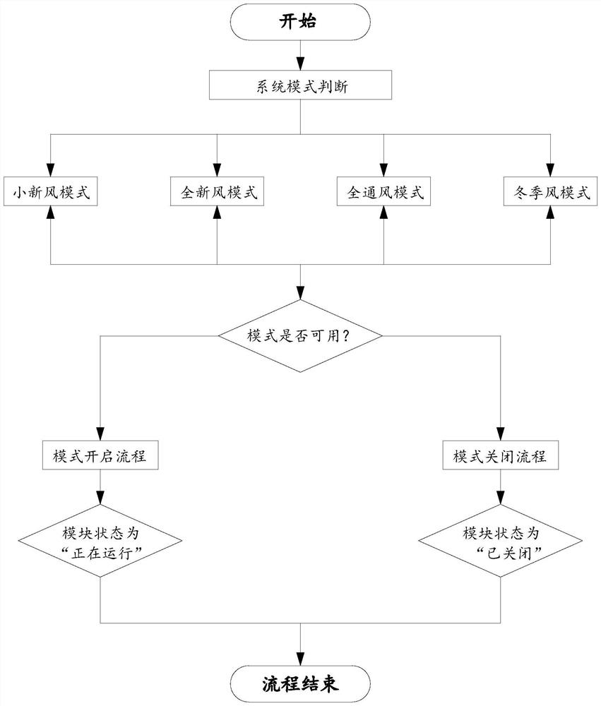
[0042] according to figure 2 As shown, this embodiment proposes a control method for a multi-working condition terminal air-conditioning system, including the following steps:

[0043] Obtain the outdoor air enthalpy value, indoor average enthalpy value, outdoor temperature, supply air temperature setting value, outdoor minimum temperature setting value and indoor dew point temperature parameters, judge the wind side system mode according to the above parameters, and control the terminal air conditioner according to the judgment results The system executes the corresponding wind side mode under the corresponding working conditions;

[0044] Specifically:

[0045] When the outdoor air enthalpy value Hw ≥ the indoor average enthalpy value Ha, the small fresh air mode will be implemented, the air module status will be "opening", and the delay reset operation will be performed simultaneously;

[0046] When the outdoor air enthalpy value Hw

Embodiment 3

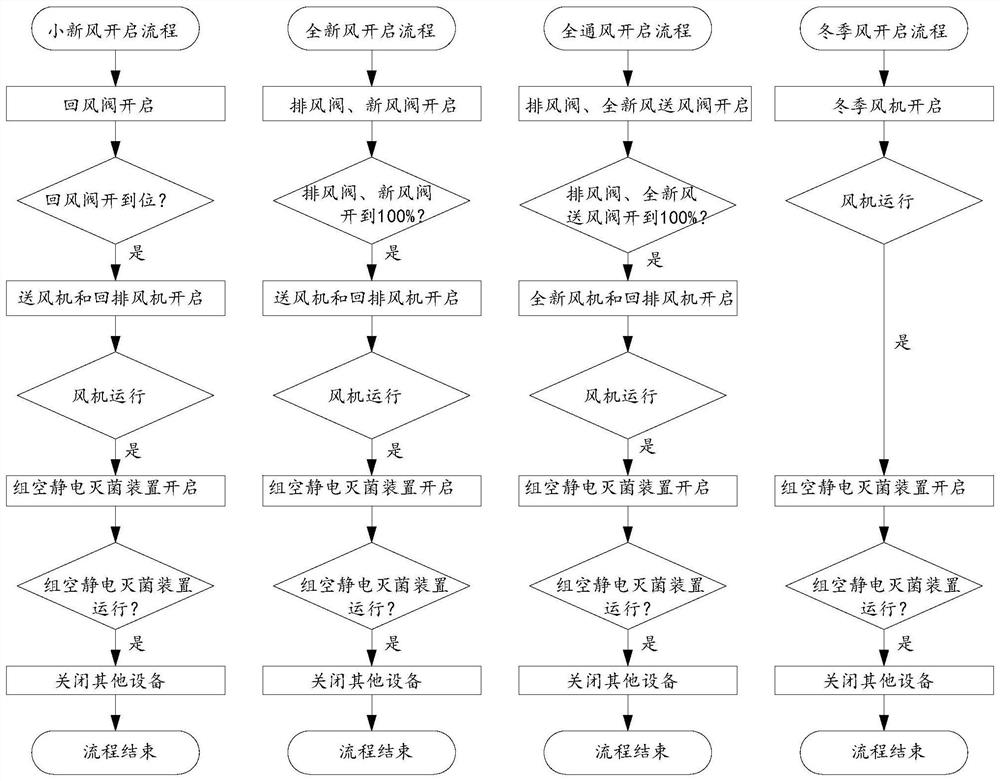
[0057] according to image 3 As shown, this embodiment proposes a control method for a terminal air-conditioning system for multi-working conditions. When the wind-side mode can be turned on, the subordinate modes included in the wind-side mode are controlled to run according to the control process of the corresponding mode. Specifically for:

[0058] When the small fresh air mode can be turned on, its control process is as follows:

[0059] The return air valve 19 is opened, and it is judged whether the return air valve 19 is opened to the maximum range;

[0060] When the air return valve 19 is opened to the maximum range, the air blower and the exhaust fan 15 of the combined air conditioning unit body 1 are controlled to perform an opening command;

[0061] When the air supply fan and the exhaust fan of the combined air conditioning unit body 1 feed back the running status, a command to start the group empty electrostatic sterilizer is issued;

[0062] When the group empt...


PUM


Abstract

The invention discloses a multi-working-condition terminal air conditioning system, a control method and a control device, and relates to the technical field of automatic control, the multi-working-condition terminal air conditioning system comprises a combined air conditioning unit body, an exhaust shaft, an air inlet shaft, a full fresh air duct, a winter air duct and a return exhaust duct, and the full fresh air duct and the winter air duct are arranged on the system air duct of the combined air conditioning unit body; the winter air duct is connected with the full fresh air duct, the full fresh air duct is connected with the air inlet shaft, and the air return and exhaust duct is connected with the air exhaust shaft. The all fresh air duct is additionally arranged on the system air duct of the combined air conditioning unit body, so that a surface air cooler does not need to be arranged in a tail end air conditioning system, resistance of the surface air cooler does not exist in a transition season, power consumption of a fan for doing idle work is reduced, and the comprehensive energy efficiency of the tail end air conditioning system can be improved; the winter air duct is additionally arranged on the system air duct of the combined air conditioning unit body, so that the use requirement of small air volume in winter can be met, the comfort of a human body is improved, and the energy consumption of a tail end air conditioning system is reduced.

Description

technical field [0001] The invention relates to the technical field of automatic control, in particular to a terminal air-conditioning system for multi-working conditions, a control method and a control device. Background technique [0002] The group control system consists of a three-level network consisting of management layer (group control system software), control layer (intelligent control cabinet group), and equipment layer (units, water pumps, cooling towers, terminal fans, electric butterfly valves, various sensors, etc.). The HVAC control system is the brain of HVAC, which controls the operation of various equipment (cooling towers, water pumps, cold source units, fans, etc.) in HVAC; [0003] At present, the conventional air duct system of HVAC on the market is designed as one air supply duct and one return air duct. This type of air duct is designed according to the hotter working conditions in summer, without considering the need for air conditioners in the tran...

Claims


Application Information

Patent Timeline
IPC IPC(8): F24F1/0038F24F11/64F24F11/65
CPCF24F1/0038F24F11/64F24F11/65
Inventor 李宏波李业明王升姜春苗丁文涛杨金龙
Owner GREE ELECTRIC APPLIANCES INC OF ZHUHAI
Features
  • R&D
  • Intellectual Property
  • Life Sciences
  • Materials
  • Tech Scout
  • Unparalleled Data Quality
  • Higher Quality Content
  • 60% Fewer Hallucinations
Learn More