Eureka AIR delivers breakthrough ideas for toughest innovation challenges, trusted by R&D personnel around the world.

High-power pulse laser power supply circuit

A pulsed laser and power circuit technology, applied in the electrical field, can solve the problems of current stability ripple, the real-time response of the circuit can not meet the high dynamic use environment, etc., which is beneficial to the reduction of the ripple and the improvement of the current density. Effect

Active Publication Date: 2021-06-04
SHANGHAI INST OF SPACE POWER SOURCES
View PDF10 Cites 3 Cited by
  • Summary
  • Abstract
  • Description
  • Claims
  • Application Information

AI Technical Summary

Problems solved by technology

The existing high-power pulse power supply implementation scheme is realized by interleaved parallel BUCK constant current source technology and energy storage capacitor linear discharge output technology. The BUCK constant current source scheme has current stability and ripple problems, and the real-time response of the circuit cannot meet high dynamic use. According to the requirements of the environment, the linear discharge scheme of the energy storage capacitor array has the problem of charging waiting time and the volume of the capacitor array, and has certain limitations in the occasions where the volume size is limited. Therefore, the present invention proposes a new high-power pulsed laser power supply implementation scheme. , to solve the high-quality power demand of high-power lasers

Method used


Image

  • High-power pulse laser power supply circuit
  • High-power pulse laser power supply circuit
  • High-power pulse laser power supply circuit

Examples


Embodiment Construction

[0022] The present invention will be further elaborated below in conjunction with the accompanying drawings.

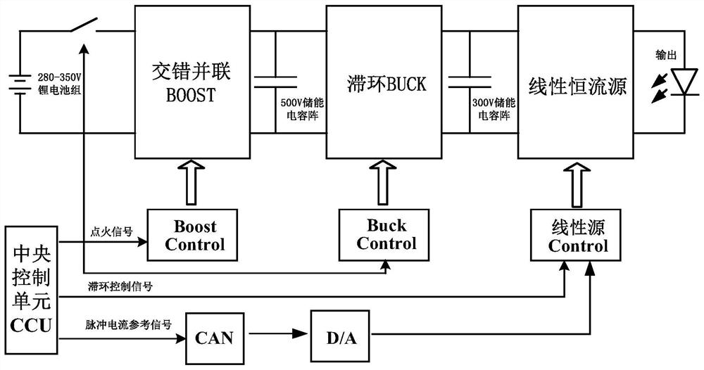
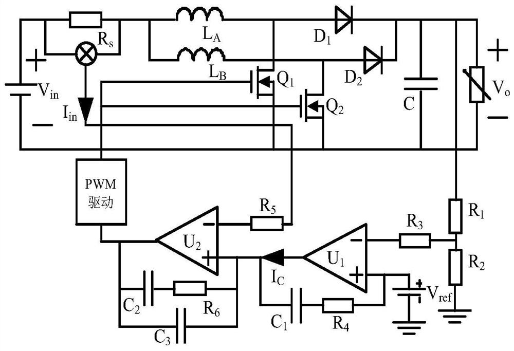
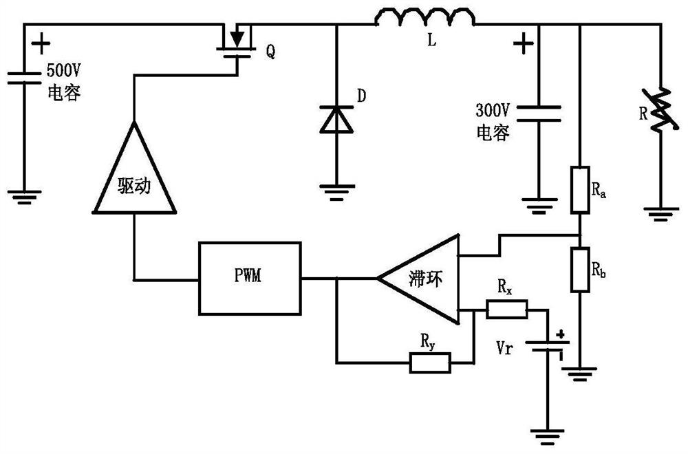
[0023] A high-power pulse laser power supply implementation scheme proposed by the present invention, the overall structure of the circuit is as follows figure 1 As shown, the main circuit includes a DC lithium battery pack, an interleaved parallel BOOST circuit, a 500V energy storage capacitor array, a hysteresis loop BUCK circuit, a 300V energy storage capacitor array, a linear constant current source circuit, and a diode array load. The control part includes a BOOST circuit control module , BUCK circuit control module, linear constant current source control module, CAN communication and D / A digital-to-analog conversion module. The high-power pulsed laser power supply controls the interleaved parallel BOOST circuit, the hysteresis BUCK circuit and the linear constant current source circuit respectively through the ignition signal sent by the central control unit CCU...


PUM


Abstract

The invention provides a high-power pulse laser power supply circuit, which comprises an interleaved BOOST and a control part for receiving a CCU ignition signal, boosting the electric energy of a lithium battery through average current control, storing the boosted electric energy in a 500V capacitor array, and providing an output environment for a back-stage BUCK+ linear constant current source; a hysteresis BUCK circuit and a control part thereof for receiving a CCU hysteresis control signal to start, rapidly charging a 300V energy storage capacitor and cooperatively outputting with a linear constant current source, and controlling the voltage of the 300V capacitor within a certain hysteresis width through voltage hysteresis control; and a linear constant current source circuit and a control part thereof for receiving a CCU pulse current reference signal and outputting pulse current with certain frequency, pulse width and amplitude required by a laser load through an internal linear modulation network, wherein the interior of the linear constant current source circuit also has an overcurrent protection function, and a protection switch tube is closed through an overcurrent protection network when an overcurrent fault occurs. The problem of a driving power supply of an existing high-power laser is solved, the circuit and the control composition are simple, the realization is convenient and reliable and the circuit has been verified by a principle prototype.

Description

technical field [0001] The invention belongs to the field of electricity and relates to a realization scheme of a high-power pulsed laser power supply. Background technique [0002] Semiconductor lasers have the advantages of small size, high efficiency, good reliability and long working life, and are widely used in national defense, scientific research, medical treatment, processing and other fields. According to the power demand of semiconductor lasers, high-quality pulse current waveforms have higher requirements on the rising and falling times of rising and falling edges in terms of dynamics, and in terms of stability, current ripple and overshoot and reverse Current and so on also have higher index constraints. The existing high-power pulse power supply implementation scheme is realized by interleaved parallel BUCK constant current source technology and energy storage capacitor linear discharge output technology. The BUCK constant current source scheme has current stab...

Claims


Application Information

Patent Timeline
Patent Type & Authority Applications(China)
IPC IPC(8): H01S3/09H02H3/087H02H7/12H02M1/14H02M3/156H02M3/158
CPCH01S3/09H01S3/0903H02M3/1584H02M3/156H02M1/14H02H7/1213H02H3/087
Inventor 邹锦浪蔡婧璐沈昂曹佳君覃思明胡律韩业华
Owner SHANGHAI INST OF SPACE POWER SOURCES
Why Eureka
Eureka Blog
Learn More