Supercharge Your Innovation With Domain-Expert AI Agents!

Special vacuum system for melt-blown material

A vacuum system and melt-blown technology, which is applied in the field of melt-blown material production, can solve problems such as insufficient vacuum, difficulty in vacuuming, and fluctuations in material strips, and achieve the effects of reducing liquid backflow, increasing utilization efficiency, and increasing power

Active Publication Date: 2021-06-08
HUNAN SHENGJIN NEW MATERIAL
View PDF6 Cites 0 Cited by
  • Summary
  • Abstract
  • Description
  • Claims
  • Application Information

AI Technical Summary

Problems solved by technology

[0002] The low VOC of melt blown material is a very important indicator, and one of the key processes to control the VOC of melt blown material is to control the extremely high vacuum degree. The change of vacuum will have a great impact on the production of melt blown material, resulting in the fluctuation of melt index ;A stable vacuum is of great significance for the production of melt-blown materials with stable melt fingers. Due to the excellent fluidity of the melt-blown materials, the air in the materials will cause fluctuations in the material strips during production, causing broken strips to affect production
[0003] When the VOC substances in the melt-blown material are extracted, they will condense into liquid. The traditional water ring vacuum pump cannot separate the condensate, and it will be discharged with the waste water, causing environmental pollution, which does not meet the requirements of environmental protection; and because the vacuum system contains a large amount of condensation It is very difficult to vacuumize the water, and the traditional water ring vacuum pump cannot meet the required vacuum degree when working, and cannot guarantee the stability of the vacuum system

Method used


Image

  • Special vacuum system for melt-blown material
  • Special vacuum system for melt-blown material
  • Special vacuum system for melt-blown material

Examples


Embodiment Construction

[0031] In order to enable those skilled in the art to better understand the technical solution of the present invention, the present invention will be described in detail below in conjunction with the accompanying drawings. The description in this part is only exemplary and explanatory, and should not have any limiting effect on the protection scope of the present invention. .

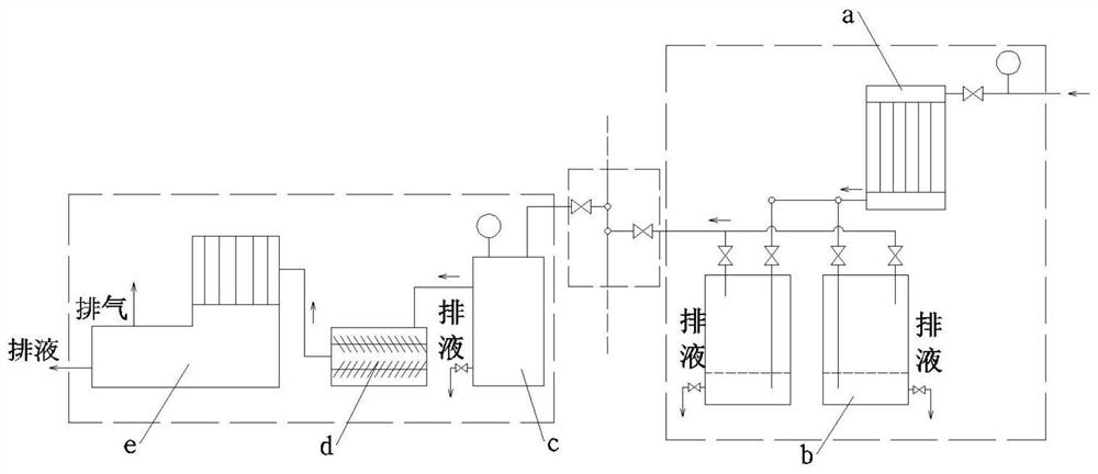
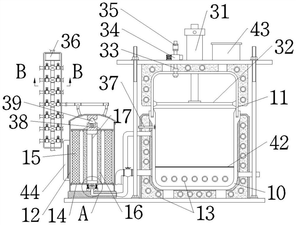
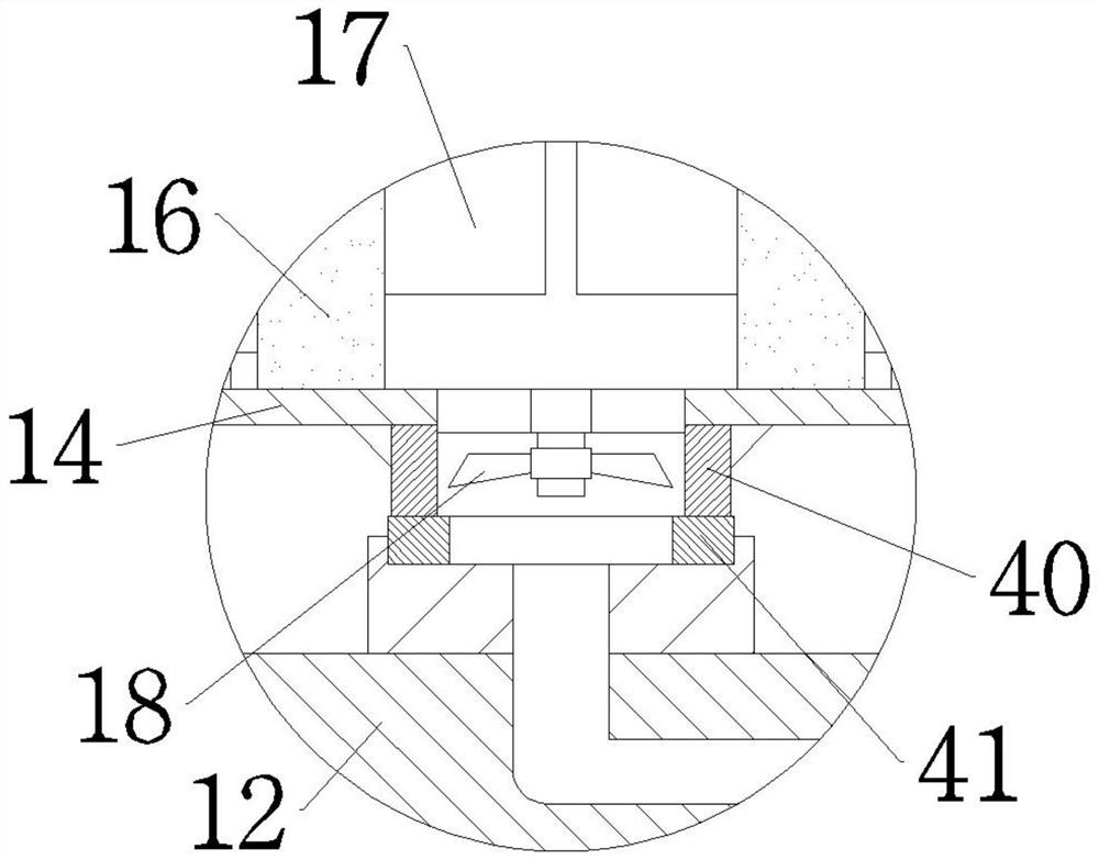
[0032] As attached to the manual Figure 1-7 As shown, the specific structure of the present invention is: a special vacuum system for melt-blown materials, including a vacuum demand part, a connecting pipeline part, and a vacuum supply part connected according to the direction of gas movement. device a and impurity removal equipment b; the vacuum supply part includes an air storage tank c, a screw vacuum pump d, and a cooler e connected in accordance with the airflow direction; the connecting pipeline part includes an intermediate main pipe and a vacuum demand part and a vacuum supply part connected ...


PUM


Abstract

The invention discloses a special vacuum system special for melt-blown materials, and belongs to the field of melt-blown material production, the vacuum system comprises a vacuum demand part, a connecting pipeline part and a vacuum supply part which are connected according to the gas movement direction, and the vacuum demand part comprises a condenser a and impurity removal equipment b which are connected according to the gas flow direction; the vacuum supply part comprises an air storage tank c, a screw vacuum pump d and a cooler e which are connected according to the airflow direction; a plurality of vacuum demand parts can operate at the same time, the working efficiency is improved, the needed vacuum degree is achieved, multiple stages of storage tanks are arranged to collect condensate, it is guaranteed that pumped gas is in a clean state when reaching the screw vacuum pump d, long-term stable operation of the system is effectively guaranteed, exhausted gas meets the environment-friendly requirement, and the multi-stage storage tank is matched with the cooler e and the filter screen system, so that when accidental material overflowing occurs and resin enters a vacuum pipeline, a subsequent pipeline is not influenced, and quick cleaning and production recovery can be realized.

Description

technical field [0001] The invention belongs to the field of melt blown material production, in particular to a special vacuum system for melt blown material. Background technique [0002] The low VOC of melt blown material is a very important indicator, and one of the key processes to control the VOC of melt blown material is to control the extremely high vacuum degree. The change of vacuum will have a great impact on the production of melt blown material, resulting in the fluctuation of melt index ; Stable vacuum is of great significance for the production of melt-blown materials with stable melt fingers. Due to the excellent fluidity of melt-blown materials, gas in the materials will cause fluctuations in the material strips during production, causing broken strips to affect production. [0003] When the VOC substances in the melt-blown material are extracted, they will condense into liquid. The traditional water ring vacuum pump cannot separate the condensate, and it wil...

Claims


Application Information

Patent Timeline
Patent Type & Authority Applications(China)
IPC IPC(8): B01J3/00B01D29/03
CPCB01J3/006B01J3/002B01D29/03Y02W30/62
Inventor 罗志宏黄红忠易正龙
Owner HUNAN SHENGJIN NEW MATERIAL
Features
  • R&D
  • Intellectual Property
  • Life Sciences
  • Materials
  • Tech Scout
  • Unparalleled Data Quality
  • Higher Quality Content
  • 60% Fewer Hallucinations
Learn More