Finishing head for die repairing machine tool

A mold and machine tool technology, applied in the field of trimming head, can solve the problems of rising production costs, short mold life, low manufacturing precision, etc., and achieve the effects of improving processing quality, convenient operation, and shortening moving time

Inactive Publication Date: 2021-06-08
郜欣
View PDF0 Cites 0 Cited by
  • Summary
  • Abstract
  • Description
  • Claims
  • Application Information

AI Technical Summary

Problems solved by technology

my country's mold industry has developed rapidly in recent years and has become one of the top three mold producing countries in the world. However, there is still a big gap between my country's mold industry and foreign advanced mold production levels, mainly in the long manufacturing cycle, low manufacturing precision, and mold production. In terms of short life, the problem of short mold life is particularly prominent, which directly leads to the waste of resources and the increase of production costs. Therefore, repair and reuse the failed molds to prolong the service life of the molds, thereby recovering unnecessary losses in production. , will greatly promote the development of industry and the national economy, and have significant economic benefits and social significance

Method used


Image

  • Finishing head for die repairing machine tool
  • Finishing head for die repairing machine tool
  • Finishing head for die repairing machine tool

Examples


Embodiment Construction

[0034] The present invention will be further described below in conjunction with accompanying drawing and specific embodiment, and the schematic embodiment of the present invention and explanation are used for explaining the present invention, but not as limiting the present invention.

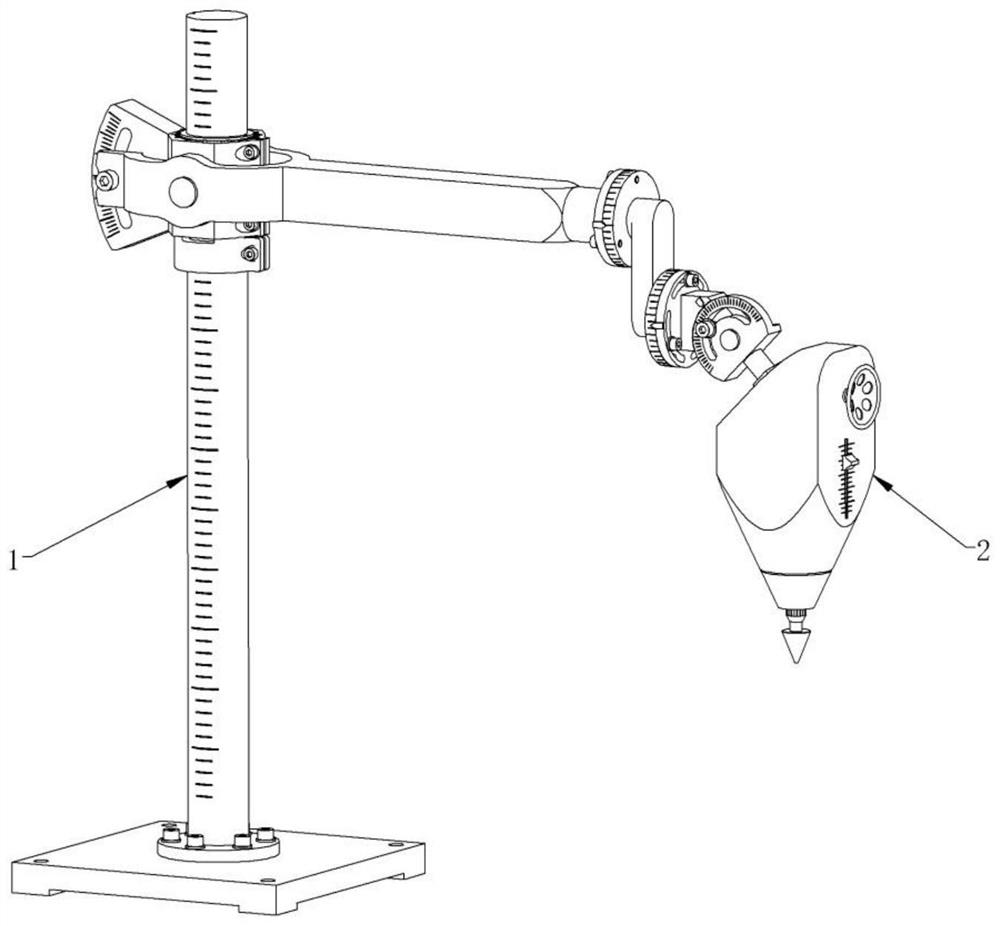
[0035] Such as figure 1 , figure 2 As shown, the mold repair machine tool includes a positioning frame mechanism 1 and a trimming head mechanism 2, which is characterized in that: the positioning frame mechanism 1 has six degrees of freedom in space, and each movable joint is provided with a scale, and the trimming head mechanism 2 is manually operated. There are two feeding methods: feeding and thermal stress feeding, and it is fastened to the end of the positioning frame mechanism 1 for repairing the surface of the mold.

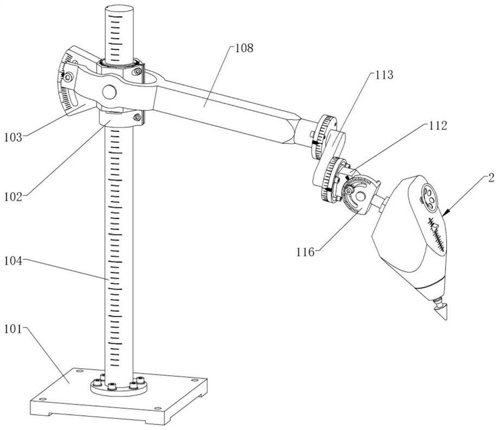
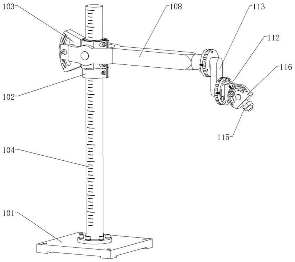
[0036] Such as Figure 3 to Figure 6 As shown, the positioning frame mechanism 1 includes a base 101, a positioning sleeve 102, a sliding sleeve 103, a column 104, a se...


PUM


Abstract

The invention discloses a finishing head for a die repairing machine tool. The finishing head comprises a shell, a worm wheel, a central gear, an inner gear ring, planetary gears, a planetary carrier, a motor, a polishing head, a high-frequency electromagnetic induction coil, a thermal deformation part, a hand wheel and a worm, wherein the shell is a supporting main body, and the motor drives the polishing head to rotate. During manual feeding, feeding and retreating of the polishing head can be realized by rotating the hand wheel and through a fixed-axis gear train composed of the worm wheel, the central gear, the inner gear ring, the planetary gears, the planetary carrier, a moving shaft, a threaded shaft, a chain, a first chain wheel, a second chain wheel and the worm; during manual feeding, the moving speed of the polishing head is high, during thermal stress feeding, a feeding sliding block can be pushed rightwards, then the thermal deformation part is heated through the high-frequency electromagnetic induction coil, and micro feeding of the polishing head is realized according to the principle of thermal expansion and cold contraction; and manual feeding can be adopted in idle stroke, so that the moving time of the polishing head is shortened, and thermal stress feeding can be adopted in finishing of the surface of a die, so that the machining quality of the surface of the die is improved.

Description

technical field [0001] The invention relates to the field of mechanical processing, in particular to a trimming head used in a mold repair machine tool. Background technique [0002] Molds play an extremely important role in modern industry, and the quality of molds directly determines the quality of products. my country's mold industry has developed rapidly in recent years and has become one of the top three mold producing countries in the world. However, there is still a big gap between my country's mold industry and foreign advanced mold production levels, mainly in the long manufacturing cycle, low manufacturing precision, and mold production. In terms of short life, the problem of short mold life is particularly prominent, which directly leads to the waste of resources and the increase of production costs. Therefore, repair and reuse the failed molds to prolong the service life of the molds, thereby recovering unnecessary losses in production. , will greatly promote the ...

Claims


Application Information

Patent Timeline
Patent Type & Authority Applications(China)
IPC IPC(8): B24B41/00B24B19/20B24B47/20B24B47/12
CPCB24B19/20B24B41/002B24B47/12B24B47/20
Inventor 不公告发明人
Owner 郜欣
Why Eureka
Try Eureka