
Concrete long-distance linear distribution system and method

A cloth system and long-distance technology, applied in the direction of supply devices, manufacturing tools, etc., can solve the problems of small cloth radius, insufficient cloth precision, large equipment investment, etc., and achieve the effect of increasing the straight line distance, precision and continuous operation

Active Publication Date: 2021-06-08
广东康酷瑞装配式建筑有限公司
View PDF8 Cites 0 Cited by
  • Summary
  • Abstract
  • Description
  • Claims
  • Application Information

AI Technical Summary

Problems solved by technology

[0002] At present, the prefabricated construction industry is developing very rapidly, and various manufacturers have developed various types of concrete pouring equipment. However, the existing concrete pouring methods in engineering buildings are all centered on the distribution machine, using the rotation of the arm to move in the circumferential direction. It is impossible to achieve continuous and accurate pouring along the straight line. Although the pouring speed is very fast, it cannot be used for the production of concrete components. It is only suitable for engineering buildings. Concrete component factories use hoppers for pouring. But its pouring speed is slow and far behind the production capacity of the mixing system
This leads to large equipment investment and low output, causing many other production equipment to be idle, seriously affecting production efficiency and increasing labor costs
[0003] At the same time, at present, the production plants of prefabricated components of buildings mostly use concrete hoppers for pouring. Although the pouring efficiency has been improved through technological updates, continuous operation cannot be achieved.
Its pouring speed is still far behind the production capacity of the mixing system
If a fixed concrete placing machine is used, due to the limitation of the plant conditions, the distributing radius is small and the distributing accuracy is not enough, and a large amount of manpower is required to assist the concrete pouring operation
Moreover, the arrangement of component molds in building assembly factories is linear, which needs to form an assembly line operation, while the operating range of fixed distributing machines is circular, and its distributing efficiency cannot be effectively utilized
As a result, the pouring scheme using concrete delivery pumps combined with concrete distribution machines cannot be applied in the production of prefabricated factories

Method used


Image

  • Concrete long-distance linear distribution system and method
  • Concrete long-distance linear distribution system and method
  • Concrete long-distance linear distribution system and method

Examples


Embodiment 1

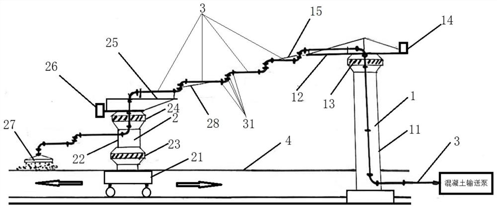
[0044] see Figure 1-2 , 5-6, according to a preferred embodiment of the present invention, a concrete long-distance linear distribution system is provided, which includes:

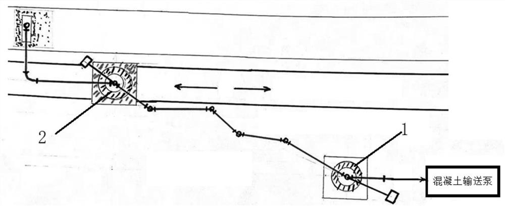
[0045] The first distribution machine 1 is fixed on the site and includes a rotatable first boom 12 and a second boom 15;

[0046] The second distribution machine 2 can reciprocate in a straight line along the first direction and includes a rotatable third arm 25 and a fourth arm 28; and

[0047]Concrete delivery pipe 3 comprises a plurality of sub-transportation pipes hinged to each other by joint 31, the first end of the concrete delivery pipe 3 ( figure 1 The right end of the middle) is connected to the concrete delivery pump, and the second end ( figure 1 Middle left end) connects pouring nozzle 27;

[0048] Wherein, the concrete conveying pipe 3 extends from the first end to the bottom of the first distribution machine 1, the top of the first distribution machine 1, the first boom 12 and the secon...

Embodiment approach

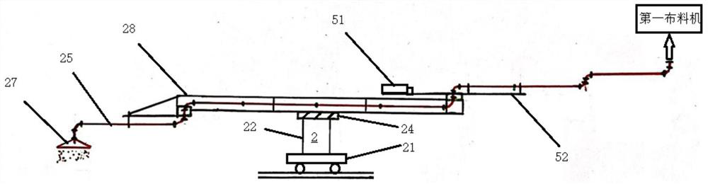
[0056] According to yet another preferred embodiment of the present invention, a first turning mechanism 13 is provided on the upper part of the first distribution machine 1 . The second distributing machine 2 includes: a traveling mechanism 21 arranged at the bottom; a column 22 arranged on the traveling mechanism 21; a second rotary mechanism 24 arranged on the top of the column 22; a third rotary mechanism 23 arranged on the The lower part of the column 22 ; the third arm 25 is disposed on the top of the column 22 ; and the fourth arm 28 is rotatably hinged to the second end of the third arm 25 . Preferably, the third arm 25 and the fourth arm 24 are set upside down.

[0057] It can be understood that the booms (first and second booms) of the existing stationary distribution machine 1 are defined as normal settings, as opposed to this, see figure 1 , the third arm 25 and the fourth arm 24 of the second distribution machine 2 are set upside down, thereby cooperating with th...

Embodiment 2

[0074] According to a preferred embodiment of the present invention, see figure 1 , provides a kind of walking type distributing machine 2, is characterized in that comprising:

[0075] The walking machine arranged at the bottom, 21;

[0076] A column 22 is arranged on the traveling mechanism 21;

[0077] Two rotating devices 23, 24 are respectively arranged on the upper part and the lower part of the column 22;

[0078] The first arm 25 is arranged on the column 22 and has a first end and a second end, and the first end is provided with a counterweight 26;

[0079] The second boom 28 is rotatably hinged to the two ends of the first walking distribution machine of the first boom 25; and

[0080]The concrete conveying pipe 3 has an inlet and an outlet, the inlet is arranged near the second end of the second arm 28 (the end away from the first arm 25) and is located at the first height, and the outlet is connected to the pouring nozzle 27 and at a second height, wherein the ...


PUM


Abstract

The invention discloses concrete long-distance linear distributing system. The concrete long-distance linear distributing system comprises a first distributing machine, a second material distributing machine and a concrete conveying pipe; the first distributing machine is fixedly arranged on site and comprises a first arm rod and a second arm rod which can rotate; the second material distributing machine can linearly travel in a reciprocating mode in the first direction and comprises a third arm rod and a fourth arm rod which can rotate; the concrete conveying pipe comprises a plurality of sub-conveying pipes which are mutually hinged through joints, the first end of the concrete conveying pipe is connected to a concrete conveying pump, and the second end of the concrete conveying pipe is connected to a pouring nozzle; and the plurality of sub conveying pipes between a stand column of the first material distributing machine and a stand column of the second material distributing machine can be changed between the stretching state and the folding state along with the reciprocating travelling of the second material distributing machine. A material distributing opening can move linearly at a constant speed, and accurate and continuous operation is achieved while pouring of the component is conducted.

Description

technical field [0001] The invention belongs to the field of concrete component prefabrication, and in particular relates to a system and method for long-distance linear distribution of concrete. Background technique [0002] At present, the prefabricated construction industry is developing very rapidly, and various manufacturers have developed various types of concrete pouring equipment. However, the existing concrete pouring methods in engineering buildings are all centered on the distribution machine, using the rotation of the arm to move in the circumferential direction. It is impossible to achieve continuous and accurate pouring along the straight line. Although the pouring speed is very fast, it cannot be used for the production of concrete components. It is only suitable for engineering buildings. Concrete component factories use hoppers for pouring. But its pouring speed is slow and far behind the production capacity of the mixing system. This leads to large equipme...

Claims


Application Information

Patent Timeline
Patent Type & Authority Applications(China)
IPC IPC(8): B28B13/02
CPCB28B13/021
Inventor 罗虎
Owner 广东康酷瑞装配式建筑有限公司
Features
  • Generate Ideas
  • Intellectual Property
  • Life Sciences
  • Materials
  • Tech Scout
  • Unparalleled Data Quality
  • Higher Quality Content
  • 60% Fewer Hallucinations
Learn More