New energy vehicle brake sensing and pedal position active adjusting type pedal mechanism

A new energy vehicle, pedal position technology, applied in the direction of brake action starting device, brake, vehicle components, etc., can solve the problems of brake pedal feeling and brake pedal position can not be adjusted actively

Inactive Publication Date: 2021-06-08
JIANGSU UNIV OF TECH
View PDF6 Cites 5 Cited by
  • Summary
  • Abstract
  • Description
  • Claims
  • Application Information

AI Technical Summary

Problems solved by technology

[0005] In order to solve the problem that the brake pedal feel and the position of the brake pedal cannot be actively adjusted in the prio

Method used


Image

  • New energy vehicle brake sensing and pedal position active adjusting type pedal mechanism
  • New energy vehicle brake sensing and pedal position active adjusting type pedal mechanism
  • New energy vehicle brake sensing and pedal position active adjusting type pedal mechanism

Examples


Embodiment 1

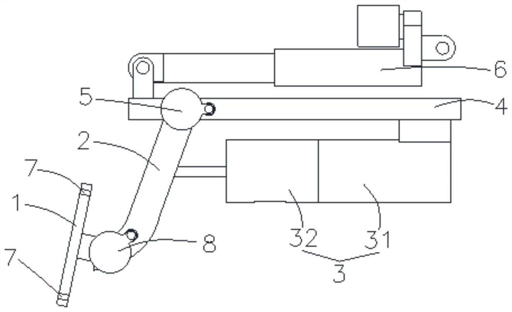
[0036] Such as Figure 1-5 As shown, a new energy vehicle brake feeling and pedal position active adjustment type pedal mechanism, including a brake pedal 1, a brake lever 2, a pedal feeling simulator 3, a bracket 4 and a push rod device 6, such as figure 1 As shown, the brake pedal 1 is rotationally connected with one end of the brake lever 2 through a stepping motor 8, and the brake pedal 1 and the brake lever 2 of the present embodiment are connected by a plug (not shown in the figure) , the stepper motor 8 is connected to the plug, the other end of the brake lever 2 is connected to the bracket 4 in rotation, an angle sensor 5 is arranged between the brake lever 2 and the bracket 4, and the angle sensor 5 is used for In order to accurately identify the braking intention, the brake pedal 1 is provided with a pre-sensing sensor 7, the pre-sensing sensor 7 is used to sense the braking intention in advance, the number of the pre-sensing sensor 7 in this embodiment is two, The ...

Embodiment 2

[0046] Such as Figure 6-8 As shown, in this embodiment, the difference from Embodiment 1 is that the push rod driver 62 includes a hydraulic cylinder housing 625, a hydraulic piston 626 and a push rod hydraulic oil circuit 627, and the hydraulic piston 626 is arranged on the hydraulic pressure In the cylinder housing 625, the end of the movable push rod 61 away from the bracket 4 is fixedly connected with the hydraulic piston 626, and the hydraulic cylinder housing 625 is fixedly arranged on the vehicle frame, and the hydraulic oil circuit 627 of the push rod is connected with the hydraulic cylinder The casing 625 is connected to drive the hydraulic piston 626 to move forward and backward; the push rod hydraulic oil circuit 627 includes a pressure accumulator 6271, a first check valve 6272 and a second check valve 6273, and the first check valve 6272 and The second one-way valve 6273 is connected in parallel with the pressure accumulator 6271. The hydraulic cylinder casing 62...


PUM


Abstract

The invention particularly relates to a new energy vehicle brake sensing and pedal position active adjusting type pedal mechanism. The mechanism comprises a brake pedal, a brake rod, a pedal sensing simulator, a support and a push rod device, wherein the brake pedal is rotationally connected with one end of the brake rod through a stepping motor, and the other end of the brake rod is rotationally connected with the support; an angle sensor is arranged between the brake rod and the support, and a pre-induction sensor is arranged on the brake pedal; the pedal feeling simulator comprises a magnetorheological fluid damper and a spring damper, and the spring damper comprises a spring shell and a damping spring arranged in the spring shell; the magnetorheological fluid damper comprises a magnetorheological fluid shell, a damping piston, magnetorheological fluid and a coil, the damping piston, the magnetorheological fluid and the coil are arranged in the magnetorheological fluid shell, the damping piston moves front and back, the magnetorheological fluid shell is fixedly connected with the spring shell and the support, and a damping piston rod penetrates through the spring shell in a sliding mode and is rotationally connected with the brake rod; the damping piston rod is provided with a limiting piece for adjusting the pre-tightening force of the damping spring; the push rod device drives the support to move back and forth.

Description

technical field [0001] The invention belongs to the technical field of vehicle braking, and in particular relates to a new energy vehicle braking feeling and pedal position active adjustment type pedal mechanism. Background technique [0002] With the rapid development of new energy vehicles, brake-by-wire has become the development trend of automobile braking. The traditional brake pedal, which directly controls the brakes of automobiles through mechanical transmission, can no longer meet the development requirements of new energy vehicles. Then there is a pedal feeling simulator for simulating the feeling of the car brake pedal, which indirectly controls the car brakes through electrical signals. [0003] The brake pedal feeling simulator is mainly used to simulate the relationship between pedal force and pedal displacement, so that the driver has a good brake pedal feel, and controls the braking state of the car brake through electrical connection to achieve more intelli...

Claims


Application Information

Patent Timeline
IPC IPC(8): B60T7/06B60T7/04B60T8/40
CPCB60T7/042B60T7/06B60T8/409
Inventor 王奎洋金一超甘宇童朱雨婕陶志远徐浩凯朱杰唐金花
Owner JIANGSU UNIV OF TECH
Why Eureka
Try Eureka