Hydraulic control device of road guardrail breakdown van

A technology for control devices and highway guardrails, which is applied to fluid pressure actuation devices, pump devices, servo meter circuits, etc., and can solve problems such as high labor intensity, time-consuming and labor-intensive problems

Pending Publication Date: 2021-06-08
徐州澳恒机械科技有限公司
View PDF0 Cites 0 Cited by
  • Summary
  • Abstract
  • Description
  • Claims
  • Application Information

AI Technical Summary

Problems solved by technology

[0003] The purpose of the present invention is to provide a hydraulic control device for a highway guardrail emergency repair vehicle to solve the

Method used


Image

  • Hydraulic control device of road guardrail breakdown van
  • Hydraulic control device of road guardrail breakdown van
  • Hydraulic control device of road guardrail breakdown van

Examples


Embodiment 1

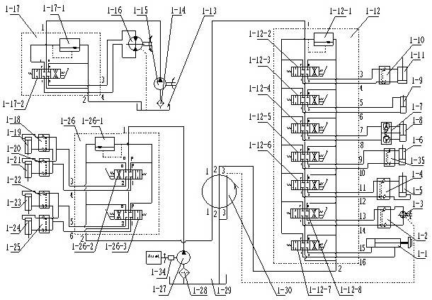
[0030] Embodiment 1: The hydraulic control device includes: rotary joint 1-30, operation controller, drilling controller, outrigger controller, oil pump assembly; the output of the oil pump assembly is to the outrigger controller, and the output of the oil pump assembly is passed through the rotary The joint 1-30 is connected to the operation controller and the drilling controller; to drive and control the operation of the pile driver.

[0031] The oil pump assembly includes: rotary joint 1-30, auxiliary oil tank 1-13, auxiliary filter screen 1-14, drilling oil pump 1-15, main oil pump 1-27, main filter screen 1-28, main oil tank 1- 29 and power take-off 1-34;

[0032] The input end of the drilling oil pump 1-15 is passed into the auxiliary oil tank 1-13 through the auxiliary filter screen 1-14, and the output end of the drilling oil pump 1-15 is connected with the No. 1 input port of the drilling control assembly valve. The No. 2 output port of the valve is connected to the ...

Embodiment 2

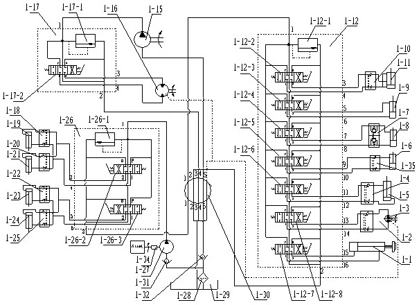
[0044] Embodiment 2: The oil pump assembly includes: rotary joint 1-30, drilling oil pump 1-15, main oil pump 1-27, main filter screen 1-28, main oil tank 1-29, main oil pump check valve 1 -31, rotary check valve 1-32 and power take-off 1-34;

[0045] The input end of the drilling oil pump 1-15 leads to the main oil tank 1-29 through the No. 4 port of the rotary joint 1-30, the rotary check valve 1-32 and the main filter screen 1-28, and the output of the drilling oil pump 1-15 The end is connected with the input port 1 of the drilling control assembly valve, and the output port 2 of the drilling control assembly valve is connected to the main oil tank 1-29 through the No. 3 port of the rotary joint 1-30; the input shaft of the main oil pump 1-27 The output shaft of the power take-off 1-34 is connected to the top, and the input gear of the power take-off 1-34 meshes with the gearbox of the automobile engine; the input end of the main oil pump 1-27 passes through the main oil p...

Embodiment 3

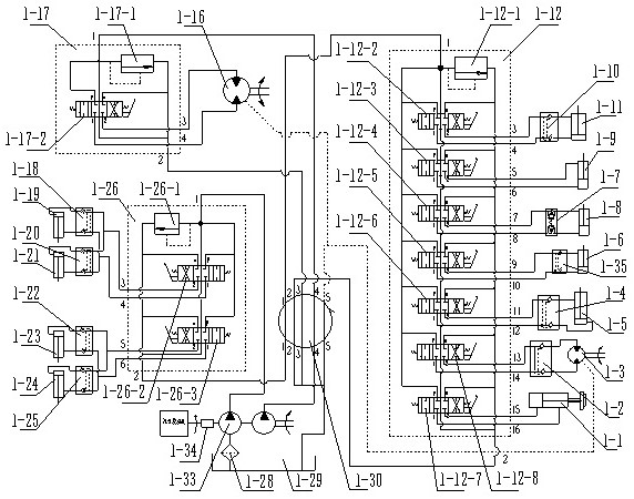
[0047] Embodiment 3: The oil pump assembly includes: a rotary joint 1-30, a main filter screen 1-28, a main oil tank 1-29, a double pump 1-33 and a power take-off 1-34;

[0048]Described duplex pump 1-33 comprises main oil pump 1-27 and borehole oil pump 1-15; Main oil pump 1-27 and borehole oil pump 1-15 are connected in series as a whole; The main filter screen 1-28 leads to the main oil tank 1-29; the output end of the drilling oil pump 1-15 of the double pump 1-33 passes through the No. 4 input and output port of the rotary joint 1-30 and the drilling control assembly valve The input port 1 is connected, and the output port 2 of the drilling control assembly valve is connected to the main oil tank 1-29 through the No. 3 port of the rotary joint 1-30; the input shaft of the main oil pump 1-27 of the double pump 1-33 is connected with The output shaft of the power take-off 1-34, the input gear of the power take-off 1-34 meshes with the gearbox of the automobile engine; The ...


PUM


Abstract

The invention discloses a hydraulic control device of a road guardrail breakdown van, and belongs to road guardrail breakdown van. The hydraulic control device comprises a swivel joint, an operation controller, a drilling controller, a supporting leg controller and an oil pump assembly; the oil pump assembly outputs to the supporting leg controller, and the supporting leg controller outputs to the swivel joint and outputs to the operation controller and the drilling controller; and a pile driver is driven and controlled to work. The hydraulic control device has the advantages that the structure is simple, the size is small, one hydraulic controller can control hydraulic components of the whole vehicle, normal operation of road repair is effectively controlled and driven, control is convenient, particularly, one hydraulic controller comprises a piling hydraulic control device and a drilling machine hydraulic control device, multiple functions of piling, pile pulling and drilling can be achieved through one device, and the labor intensity of workers is greatly reduced.

Description

technical field [0001] The invention relates to a road guardrail emergency repair vehicle, in particular to a hydraulic control device for a highway guardrail emergency repair vehicle. Background technique [0002] At present, people use highway guardrail rush repair vehicle to carry out piling or maintenance, rush repair construction to highway guardrail pile. The existing highway guardrail emergency repair vehicle can adjust the verticality of the column in the pitch direction by adjusting the pitch direction of the column, but cannot adjust the verticality of the left and right directions of the column. When using the existing highway guardrail emergency repair vehicle to carry out drilling or piling, the air motor or pneumatic impactor is used. Therefore, it is necessary to be equipped with a large air compressor installed on a special trailer to meet the working requirements of the pneumatic impactor. The guardrail emergency repair vehicle is bulky, the product is heav...

Claims


Application Information

Patent Timeline
IPC IPC(8): F15B11/17F15B13/01F15B13/02E21B7/02E21B3/02F04B23/02F04B23/04
CPCE21B3/02E21B7/024F04B23/025F04B23/04F15B11/17F15B13/01F15B13/02F15B2211/20576
Inventor 侯学礼
Owner 徐州澳恒机械科技有限公司
Why Eureka
Try Eureka