Numerical control multi-station milling machine
A milling machine and multi-station technology, applied in the field of engraving machines, can solve the problems of inability to link and synchronize, poor shoe mold matching, etc., to achieve the effect of promoting rapid recovery, high matching degree, and promoting cooling
- Summary
- Abstract
- Description
- Claims
- Application Information
AI Technical Summary
Problems solved by technology
Method used
Image
Examples
Embodiment 1
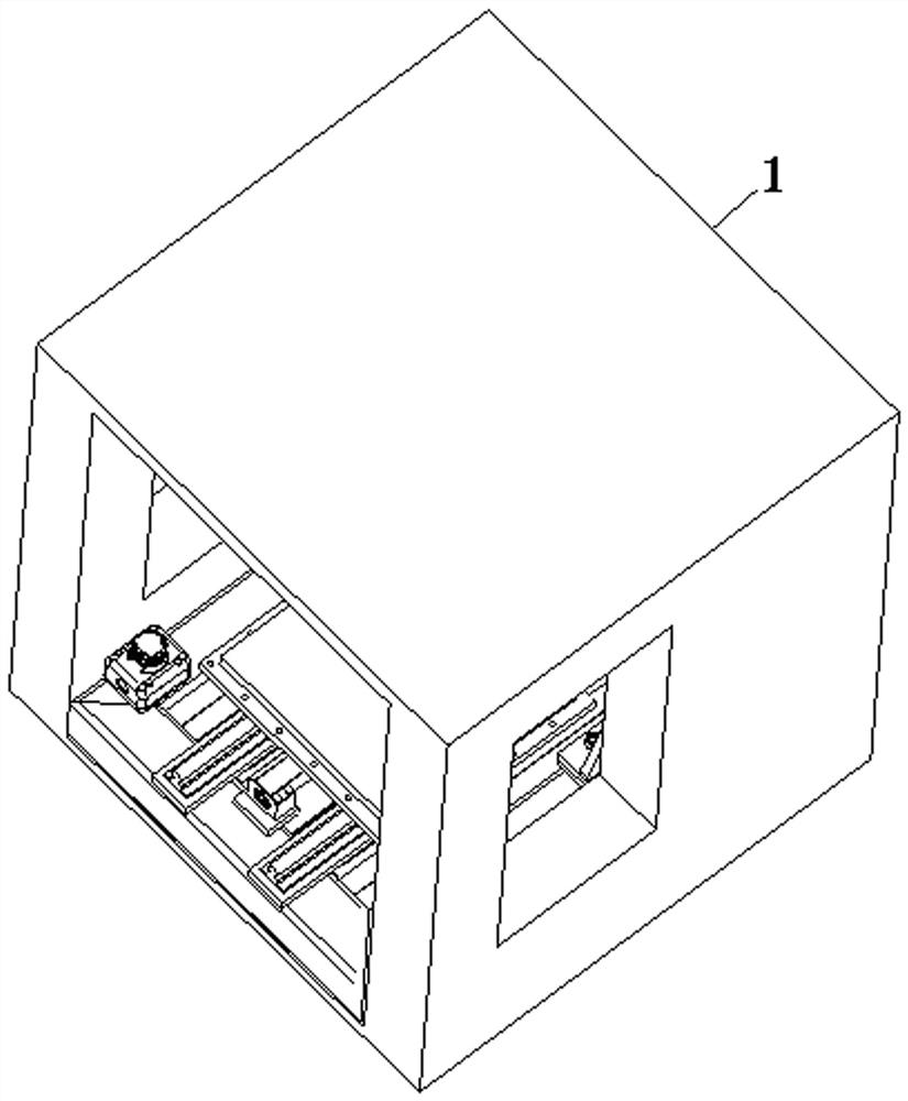
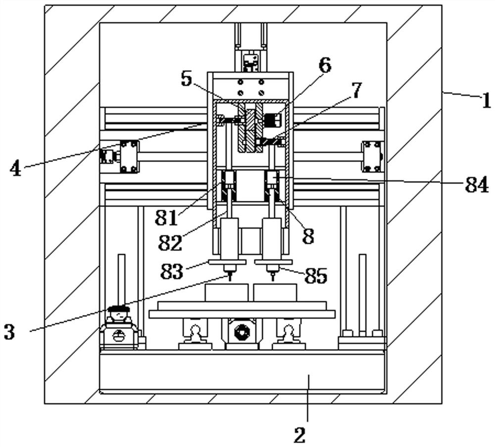
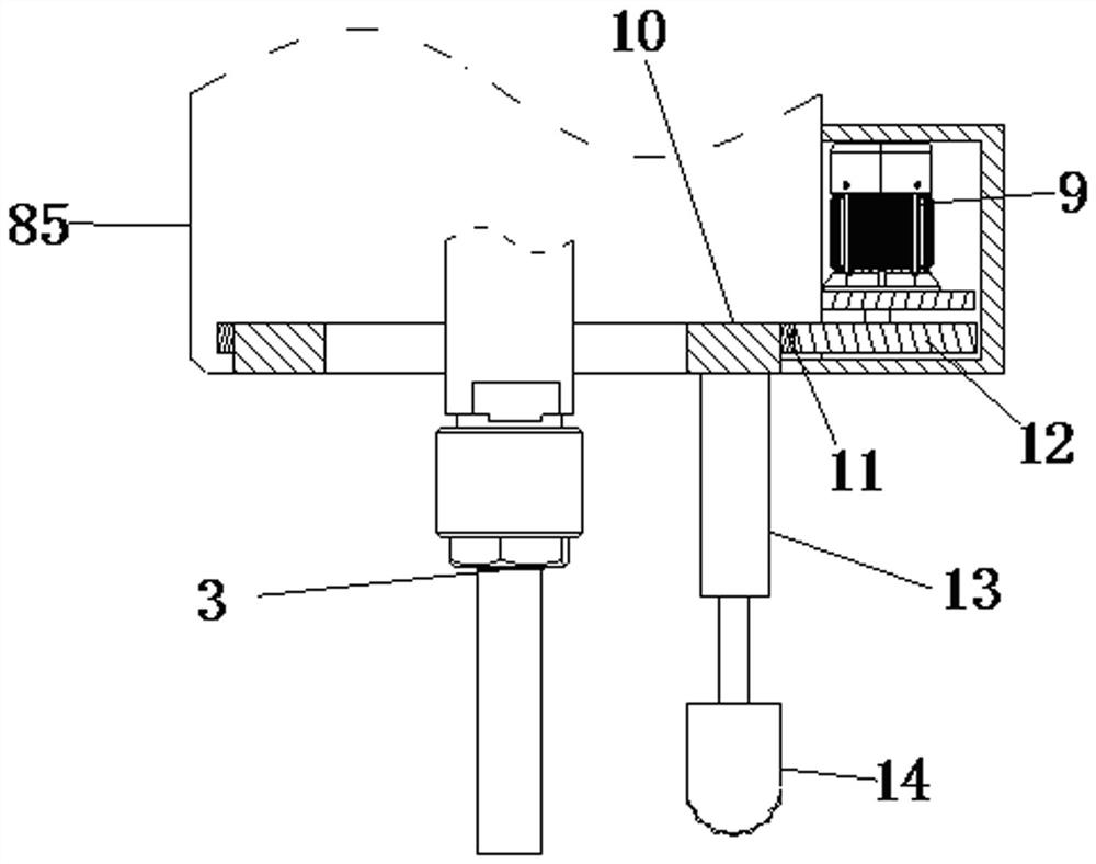
[0032] see Figure 1-6 As shown, the CNC multi-station milling machine includes a shell 1, a platen 2 and a milling cutter 3; the inner bottom surface of the shell 1 is provided with a platen 2; the top surface of the platen 2 is provided with a first shoe mold; The top surface of the platen 2 is fixedly connected with a second shoe mold close to the position of the first shoe mold, and the first shoe mold and the second shoe mold are a pair of corresponding shoe molds; the top of the platen 2 is provided with an adjusting plate 4 A pair of first gears 5 are connected to the inner rotation of the adjusting plate 4; one of the first gears 5 is fixedly connected with a first motor 6; the sides of the two first gears 5 are fixedly connected with threaded sleeves The inner thread of the threaded sleeve is connected with a screw rod 7; the inner side of the adjustment plate 4 is fixedly connected with a guide ring, and the screw rods 7 are all slidably connected to the inside of th...
Embodiment 2
[0042] see Figure 7 As shown in Comparative Example 1, another embodiment of the moving assembly is that the moving assembly 8 may also include a second adjusting block 86, a second connecting rod 87 and a second mounting plate 88; the screw rod The bottom of 7 is fixedly connected with the second adjusting block 86; the inside of the second adjusting block 86 is fixedly connected with the second telescopic rod 89; the bottom surface of the second telescopic rod 89 is connected with the second connecting rod 87; The bottom surface of the rod 87 is fixedly connected with the second mounting plate 88; the bottom surface of the second mounting plate 88 is connected with the first guide rail near the side position of the second mounting plate 88; A guide block 810; a second guide rail is fixedly connected between the two first guide blocks 810; a second guide block 811 is fixedly connected to the surface of the second guide rail; the bottom surface of the second guide block 811 i...
Embodiment 3
[0044] see Figure 8 As shown, as another embodiment of the present invention, the suction holes are all designed in an arc structure, and the suction holes are located at the bottom of the passage, and the storage tank 26 is opened, and at the same time, a storage tank 26 is opened in the inside of the passage The guide groove, the inside of the guide groove slides to connect the filter cotton 27, the side of the suction block 14 offers a diversion hole, and the diversion hole and the bottom of the storage tank 26 communicate with each other, and the mouth position of the diversion hole is provided with a plug 28; The suction hole is designed in an arc shape, so that the inhaled coolant first gathers at the bottom of the channel, and then is introduced into the channel synchronously, so that the filter cotton 27 can be uniformly set inside the channel, and the metal chips inside the coolant can be removed through the filter surface. Directly filter, the filtered metal chips w...
PUM
 Abstract
Description
Claims
Application Information
 - R&D
- Intellectual Property
- Life Sciences
- Materials
- Tech Scout
- Unparalleled Data Quality
- Higher Quality Content
- 60% Fewer Hallucinations
Browse by: Latest US Patents, China's latest patents, Technical Efficacy Thesaurus, Application Domain, Technology Topic, Popular Technical Reports.
© 2025 PatSnap. All rights reserved.Legal|Privacy policy|Modern Slavery Act Transparency Statement|Sitemap|About US| Contact US: help@patsnap.com


