Energy-saving and environment-friendly sludge and sewage biological treatment equipment and use method thereof

A biological treatment, energy saving and environmental protection technology, applied in chemical instruments and methods, water/sewage multi-stage treatment, water/sludge/sewage treatment, etc. It is difficult to deal with problems such as ensuring uniform reproduction, increasing the duration of single use, and having a simple structure.

Inactive Publication Date: 2021-06-11
河南胜凡信息科技有限公司
View PDF0 Cites 0 Cited by
  • Summary
  • Abstract
  • Description
  • Claims
  • Application Information

AI Technical Summary

Problems solved by technology

[0008] In view of the above situation, in order to overcome the defects of the prior art, the present invention provides an energy-saving and environment-friendly biological treatment of sludge sewage equipment and its use method, which effectively solves the problems of long purification time of the existing stable pond, shallow aerobic pond, poor Oxygen tank sludge is easy to age and difficult to handle

Method used


Image

  • Energy-saving and environment-friendly sludge and sewage biological treatment equipment and use method thereof
  • Energy-saving and environment-friendly sludge and sewage biological treatment equipment and use method thereof
  • Energy-saving and environment-friendly sludge and sewage biological treatment equipment and use method thereof

Examples


Embodiment 1

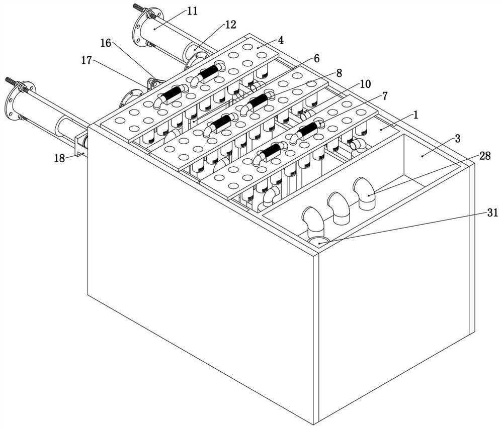
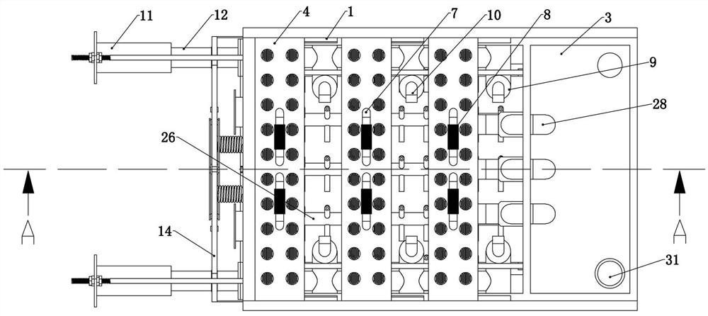
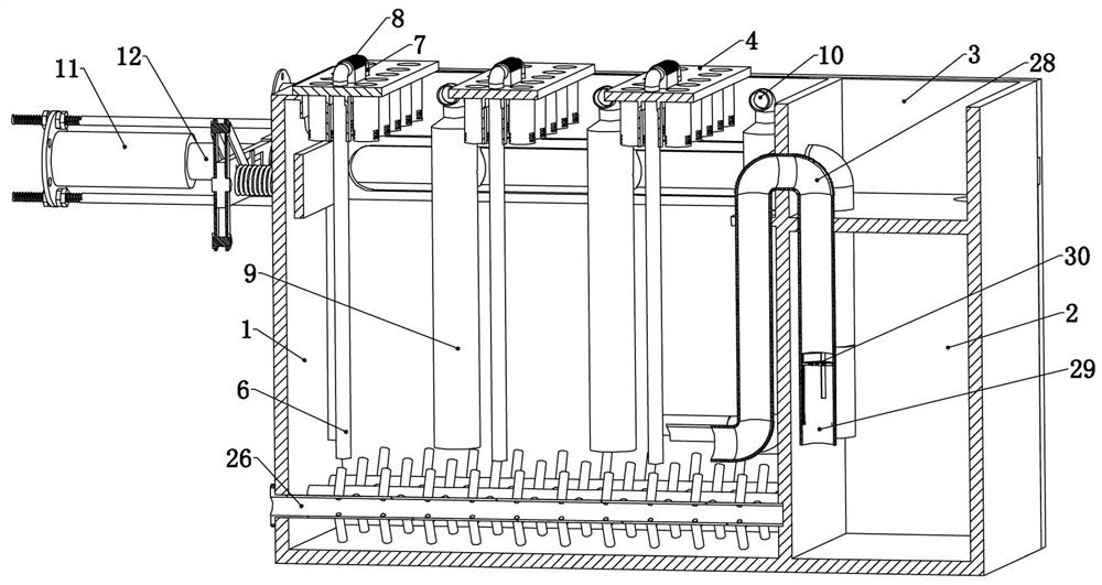
[0050]Embodiment 1, the present invention is an energy-saving and environment-friendly biological treatment sludge sewage equipment, characterized in that it includes an aerobic pool 1, the aerobic pool 1 is placed on the ground or partially buried in the soil, the aerobic pool 1 An anaerobic pool 2 is arranged on one side of the pool 1, an observation pool 3 is arranged above the anaerobic pool 2, and the anaerobic pool 2 and the observation pool 3 are connected;

[0051] A plurality of culture plates 4 are slidingly connected above the aerobic pool 1, refer to figure 1 , image 3 , Figure 5 , the described culture plate 4 is provided with a number of culture holes, each culture hole below is provided with a culture cylinder fixedly connected to the lower end surface of the culture plate 4, the bottom surface and the side of the culture cylinder are provided with through holes, and the bottom surface of the culture cylinder is located at the aerobic Under the water surface...

Embodiment 2

[0054] Embodiment 2, on the basis of Embodiment 1, the side wall of the aerobic tank 1 is fixedly connected with a telescopic cylinder 11, and the telescopic cylinder 11 is connected with an external air source, and the external air source is an aeration device , the multiple aeration pipes 9 on the same side are all in communication with the air intake pipe 12 that is slidably connected in the aerobic tank 1, and one end of the air intake pipe 12 passes through the side wall of the aerobic tank 1 and is slidably connected to the telescopic tube 11 Inside, the expansion and contraction of the intake pipe 12 can drive the synchronous movement of several connected aeration pipes 9;

[0055] A plurality of the culture plates 4 are connected to each other through the connecting plate 13, and this setting can make the multiple culture plates 4 move synchronously;

[0056] In the specific use of this embodiment, the staff needs to regularly control the expansion and contraction of t...

Embodiment 3

[0057] Embodiment three, on the basis of embodiment two, a gate valve substrate 14 is fixedly connected between the two air intake pipes 12, refer to Figure 4 The two ends of the gate valve substrate 14 are respectively fixed to be connected to the intake pipes 12 on both sides, and are located outside the aerobic tank 1. The movement of the gate valve substrate 14 can drive the intake pipe 12 to move synchronously. The gate valve substrate 14 and the The side walls of the aerobic pool 1 are connected by springs. When the springs are in the initial state, the gate valve substrate 14 is far away from the side walls of the aerobic pool 1. The gate valve plate 32 on the side wall, the side wall of the intake pipe 12 is provided with a gate valve through hole, the gate valve plate 32 can enter the intake pipe 12 through the gate valve through hole and shut off the intake pipe 12, the gate valve through hole, the gate valve plate 32 and the gate valve substrate 14 locations are eq...


PUM


Abstract

The invention relates to energy-saving and environment-friendly sludge and sewage biological treatment equipment and a use method thereof. The problems that an existing stabilization pond is long in purification time, an aerobic pond is shallow, and sludge in the aerobic pond is prone to aging and not easy to treat are effectively solved. According to the technical scheme, the equipment comprises an aerobic tank, an anaerobic tank is arranged on one side of the aerobic tank, an observation tank is arranged above the anaerobic tank, and the anaerobic tank is communicated with the observation tank; a plurality of culture plates are connected above the aerobic tank in a sliding manner, biofilm hangers are arranged below the plurality of culture plates, air supply pipes are arranged below the culture plates, the upper ends of the air supply pipes penetrate through the culture plates and are communicated with air supply U-shaped pipes fixedly connected to the culture plates, and the air supply U-shaped pipes are communicated with air pumps fixedly connected to the culture plates; and a plurality of aeration pipes are arranged on the two sides in the aerobic tank, and the upper end of each aeration pipe is fixedly communicated with a thin bent pipe. The structure is simple, the purification efficiency of the stabilization pond can be effectively improved, meanwhile, the sludge purification capacity of the aerobic pond is guaranteed, and the practicability is high.

Description

technical field [0001] The invention relates to the technical field of biological sewage treatment, in particular to an energy-saving and environment-friendly biological treatment equipment for sludge sewage and a use method thereof. Background technique [0002] Stability ponds, formerly known as oxidation ponds or biological ponds, are a general term for structures that use natural purification capabilities to treat sewage. Its purification process is similar to the self-purification process of natural water bodies. Usually, the land is properly repaired to build a pond, and dikes and anti-seepage layers are set up, and the sewage is treated by the microorganisms growing in the pond. It mainly uses the joint action of bacteria and algae to treat organic pollutants in wastewater. The stable pond sewage treatment system has the advantages of low capital investment and operating costs, no need for high-energy purification equipment, simple maintenance and repair, easy opera...

Claims


Application Information

Patent Timeline
Patent Type & Authority Applications(China)
IPC IPC(8): C02F9/14C02F3/30
CPCC02F3/30C02F9/00
Inventor 李晓阳
Owner 河南胜凡信息科技有限公司
Why Eureka
Try Eureka