Oil nozzle matching part flow testing device and method

A flow test device and a technology of even parts, which are applied in the direction of measuring device, machine/structural component test, fuel injection device, etc., can solve the problem of inability to complete the flow test of the nozzle without ring groove or step surface at the end of the needle valve, and manually adjust the accuracy Unable to guarantee, complex and cumbersome operation, etc.

Active Publication Date: 2021-06-11
FAW JIEFANG AUTOMOTIVE CO
View PDF9 Cites 0 Cited by
  • Summary
  • Abstract
  • Description
  • Claims
  • Application Information

AI Technical Summary

Problems solved by technology

[0004] However, in the current flow test device for the nozzle coupler, a stepped surface or an annular groove must be provided at the tail of the needle valve to assemble the spring, and the sliding sleeve is pressed tightly to form a high-pressure seal, so that the tail of the needle valve can be positioned at the oil-free position. In the pressure zone, it is impossible to complete the nozzle flow test without ring groove or step surface at the end of the needle valve, resulting in poor versatility; the lifting height of the needle valve is limited by the manual fine-tuning knob, the work efficiency is low and the accuracy of manual adjustment cannot be achieved. Guarantee; and when actually testing the flow rate of the nozzle assembly under different lifts, after the test nozzle is clamped, it is necessary to open the safety door of the flow test bench many times in the state of clamping and pressing, which is complicated and cumbersome.

Method used


Image

  • Oil nozzle matching part flow testing device and method
  • Oil nozzle matching part flow testing device and method
  • Oil nozzle matching part flow testing device and method

Examples


Embodiment 1

[0050] This embodiment proposes a flow test device for the nozzle assembly, which can test the flow rate of the long needle valve assembly at different lifts or at the same lift. It has good versatility, good control accuracy, and high work efficiency. High and easy to operate. The device for testing the flow rate of the nozzle assembly in this embodiment is suitable for flow testing of various nozzle assemblies similar in structure to the long needle valve assembly.

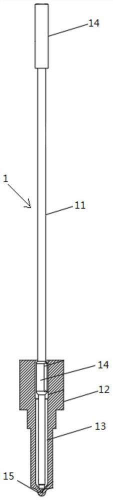
[0051] Among them, such as figure 1 As shown, the long needle valve nozzle assembly 1 includes a needle valve body 12 and a needle valve 11 inserted on the needle valve body 12, and an outer cylinder 14 is arranged at the head and tail of the needle valve 11, and the head of the needle valve 11 The outer cylinder 14 of the upper part is located in the needle valve body 12 and is in clearance fit with the needle valve body 12, and a pressure accumulator chamber 13 is formed between the needle valve 11 and the ne...

Embodiment 2

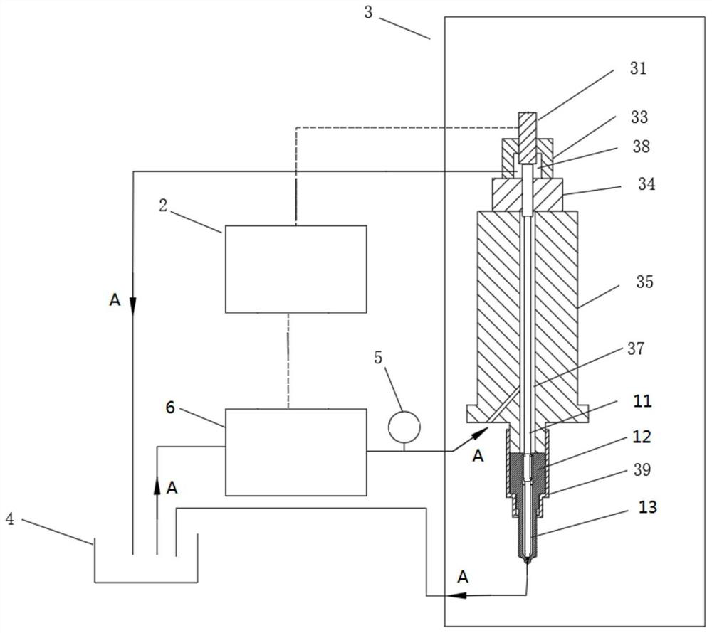
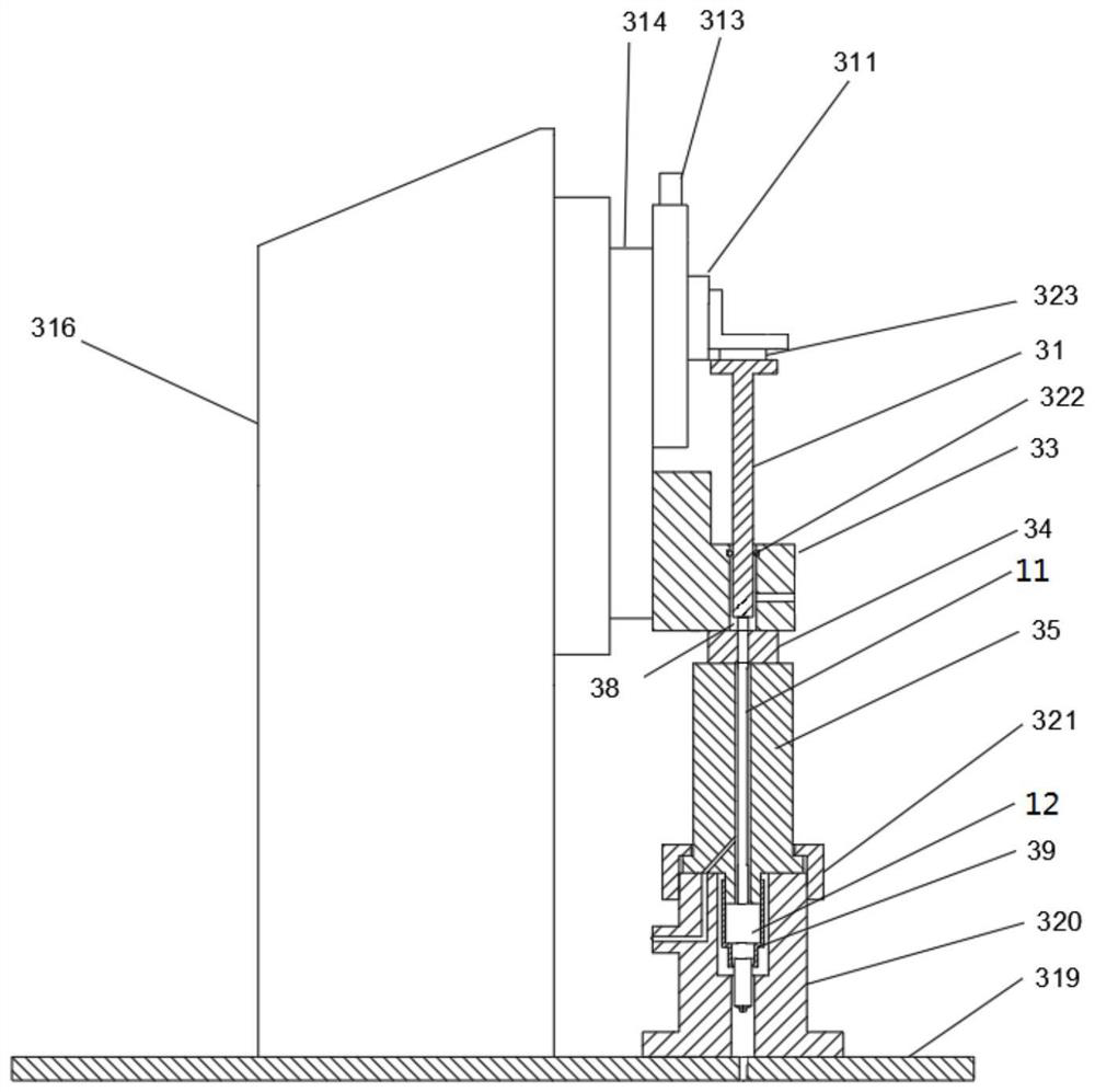
[0066] In this embodiment, a flow test device for the nozzle coupler is proposed, such as Figure 4 As shown, the difference between the nozzle assembly flow test device in this embodiment and the first embodiment is that the control method for the height of the needle valve 11 in the vertical direction is different, that is, the nozzle assembly in this embodiment The flow test device does not include the driving member 313 , the pressure sensor 323 and the needle valve plunger 31 .

[0067] Specifically, such as Figure 4 As shown, by increasing the height of the sealing slide 34 or the length of the clamp body 35, the tail of the needle valve 11 is lower than the top surface of the sealing slide 34, and at the same time, an oil return channel communicating with the oil tank 4 is provided on the test pressure head 33, Therefore, the tail of the needle valve 11 does not bear the force of the oil pressure, and the relative height of the tail of the needle valve 11 lower than t...

Embodiment 3

[0069] In this embodiment, a test method based on the flow test device of the nozzle assembly as in the first embodiment is proposed, including the following steps:

[0070] S1: the control system 2 controls the operation of the driving member 313, so that the driving member 313 drives the needle valve ejector rod 31 to move vertically downward, so that the needle valve ejector rod 31 presses against the tail of the needle valve 11;

[0071] S2: The control system 2 controls the oil supply assembly 6 to supply test oil with pressure value and temperature value into the pressure chamber 37, and the test oil in the pressure chamber 37 can pass through the gap between the outer cylinder 14 at the head of the needle valve 11 and the needle valve body 12. The gap between them flows into the accumulator chamber 13, and a tapered seal is formed between the head of the needle valve 11 and the bottom end of the needle valve body 12, so that the head of the needle valve 11 can bear the o...


PUM


Abstract

The invention discloses an oil nozzle matching part flow testing device and method, and belongs to the technical field of oil nozzle flow testing. The oil nozzle matching part flow testing device comprises a clamping assembly, an oil supply assembly, a driving part and a control system. The clamping assembly comprises a clamp body, a sealing sliding plate, a testing pressure head and a needle valve ejector rod, the needle valve ejector rod is movably arranged on the testing pressure head in a penetrating mode, the tail of a needle valve sequentially penetrates into the clamp body, the sealing sliding plate and the testing pressure head and abuts against the bottom end of the needle valve ejector rod, and an oil return cavity is formed among the needle valve ejector rod, the testing pressure head and the needle valve. A pressure cavity is formed between the needle valve and the clamp body. One end of the oil supply assembly communicates with an oil tank, the other end of the oil supply assembly communicates with a pressure cavity, and a flowmeter is arranged between the oil supply assembly and the pressure cavity. The driving part is in driving connection with the needle valve ejector rod and used for driving the needle valve ejector rod to move in the vertical direction, so that the needle valve rises to the preset lift range. The control system is separately in control connection with the oil supply assembly and the driving part. The oil nozzle matching part flow testing device and method have the beneficial effects of being good in universality and high in working efficiency.

Description

technical field [0001] The invention relates to the technical field of oil nozzle flow testing, in particular to a flow testing device and method for an oil nozzle assembly. Background technique [0002] In the research and development process of the fuel injector, it is necessary to test the actual flow value of the nozzle of the fuel injector at different lifts to complete the design parameter verification of the nozzle; and to test the nozzle at a certain fixed lift during the manufacturing process The flow rate is to meet the production quality consistency of the nozzle. Among them, the nozzle is usually a long needle valve nozzle assembly, and the flow test of the long needle valve nozzle assembly needs to be completed by the nozzle assembly flow test device. Among them, the flow test refers to lifting the needle valve of the long needle valve nozzle assembly to a certain height lift, so that the oil circuit where the long needle valve nozzle assembly to be tested is l...

Claims


Application Information

Patent Timeline
Patent Type & Authority Applications(China)
IPC IPC(8): F02M65/00
CPCF02M65/00F02M65/001F02M65/005
Inventor 栾纪杰
Owner FAW JIEFANG AUTOMOTIVE CO
Why Eureka
Try Eureka