
A magnetic induction monitoring device for rock formation subsidence and its operating method

A monitoring device, magnetic induction technology, applied in the direction of measuring device, surveying and navigation, height/horizontal measurement, etc., can solve the problem that the monitoring device cannot be stably fixed on the rock wall of the monitoring hole for a long time, cannot be recycled and reused, and cannot be adjusted again, and achieves Significant economic benefits, simple structure, and the effect of recycling

Active Publication Date: 2021-10-22
CHINA UNIV OF MINING & TECH
View PDF0 Cites 0 Cited by
  • Summary
  • Abstract
  • Description
  • Claims
  • Application Information

AI Technical Summary

Problems solved by technology

[0005] In view of the above analysis, the present invention aims to provide a rock formation subsidence magnetic induction monitoring device and its operation method to solve the problem that the existing monitoring device cannot be stably fixed on the rock wall of the monitoring hole for a long time, and cannot be recycled and reused, and once the subsidence magnetic induction One or more of the problem that the ring position is installed incorrectly, cannot be adjusted again, and the cost is high

Method used


Image

  • A magnetic induction monitoring device for rock formation subsidence and its operating method
  • A magnetic induction monitoring device for rock formation subsidence and its operating method
  • A magnetic induction monitoring device for rock formation subsidence and its operating method

Examples


Embodiment 1

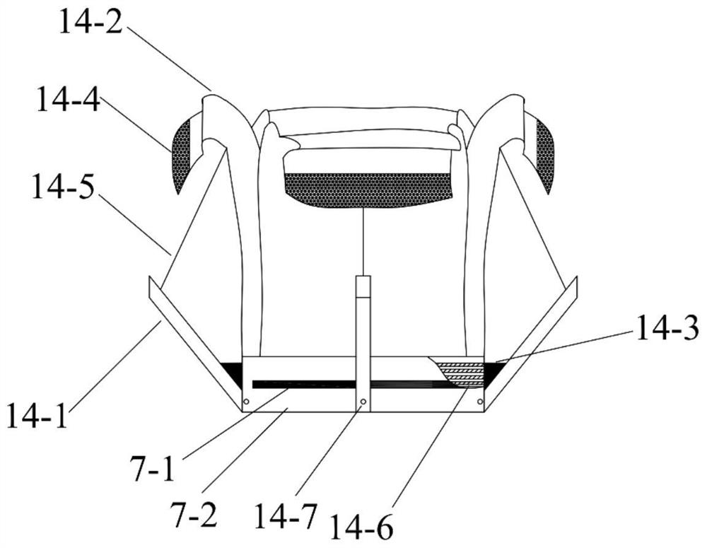
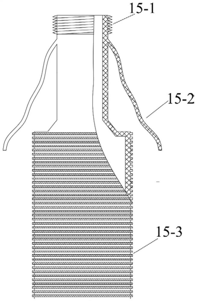
[0065] A specific embodiment of the present invention discloses a rock formation subsidence magnetic induction monitoring device, such as Figure 1-2 As shown, the rock formation subsidence magnetic induction monitoring device includes a subsidence magnetic ring assembly 14 and an installation conduit 15. The subsidence magnetic ring assembly 14 is installed on the drill pipe of the drilling rig through the installation conduit 15, and the drill pipe is used to rotate, lift, fall and cooperate with the installation conduit 15 to make the The anchor hoop assembly shrinks and expands, and then realizes the installation and recovery of the subsidence magnetic ring assembly 14, which overcomes the defect that the subsidence magnetic ring cannot be recovered without damage after the monitoring of the existing monitoring method.

[0066] The subsidence magnetic ring assembly 14 includes a magnetic induction iron ring 7-1, a magnetic ring sleeve 7-2 and an anchor hoop assembly, the ma...

Embodiment 2

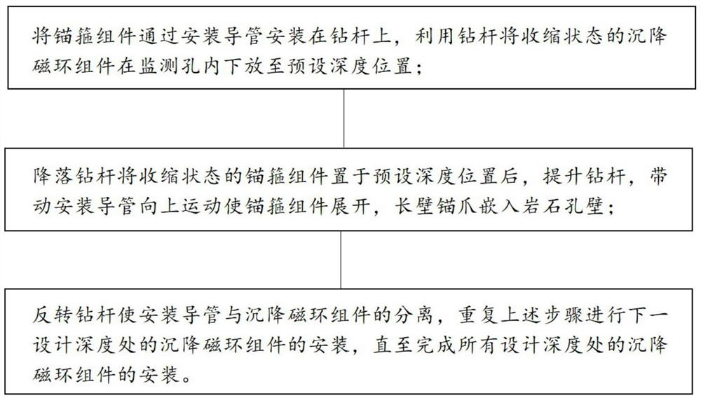
[0100] Yet another specific embodiment of the present invention discloses a method for monitoring the dynamic development of overburden mining and separation layers, the steps of which are as follows: Figure 7 As shown, the monitoring method shown includes the following steps:

[0101] S1. Determine the installation depth of the subsidence magnetic ring based on the range of the detachment development zone; this step is specifically:

[0102] The mining of the coal seam leads to stress failure of the original overlying rock, and the overlying rock on the coal seam will form a water-conducting fracture area and a separation layer development area. As shown in 8, the separation layer development area ranges from the bottom interface of the Quaternary soil layer to the top interface of the water-conducting fracture zone , according to the following formula to calculate the development depth H of the detachment layer s :

[0103] h s =H c -H f

[0104] Where: H s is the deve...


PUM


Abstract

This patent relates to a magnetic induction monitoring device for rock formation subsidence, which includes a subsidence magnetic ring assembly and an installation conduit. Set on the outer circumference of the magnetic ring sleeve, it has a contracted state and an expanded state; the anchor hoop assembly in the contracted state can move in the monitoring hole, and the anchor hoop assembly in the expanded state is at least two vertically from the wall of the monitoring hole. The two ends of the installation conduit are respectively connected with the drill pipe and the magnetic ring sleeve, and the anchor hoop assembly is in a contracted state and an expanded state through the drill pipe and the installation pipe to realize the installation and recovery of the subsidence magnetic ring assembly. The invention has simple structure and convenient operation. It can not only be firmly fixed on the wall of the monitoring hole for a long time, but also can be removed from the monitoring hole after the monitoring is completed, so as to realize repeated use, significantly reduce the cost, and have remarkable economic benefits.

Description

technical field [0001] The invention belongs to the technical field of coal mine separation layer settlement monitoring devices, and in particular relates to a rock layer settlement magnetic induction monitoring device and an operating method thereof. Background technique [0002] Different depositional times and depositional environments will result in differences in formation lithology and thickness. When the coal seam is mined, the destruction of the original rock stress of the overlying rock leads to inconsistent settlement deformation of each stratum, thus forming a separation space between the strata. On the one hand, under the action of negative pressure, a large amount of water resources in the overlying rock aquifer accumulates in the cavity of the separation layer. When the scale develops to a certain extent, instantaneous water inrush accidents from the separation layer will occur, threatening the safe mining of the mine working face. On the other hand, the closu...

Claims


Application Information

Patent Timeline
Patent Type & Authority Patents(China)
IPC IPC(8): G01C5/00
CPCG01C5/00
Inventor 李文平陈维池秦伟吕振猛王启庆杨玉茹
Owner CHINA UNIV OF MINING & TECH
Learn More