
Device and method for detecting short-circuit fault point of finished printed circuit board

A printed circuit board and short-circuit fault technology is applied in the field of short-circuit fault point detection devices for finished printed circuit boards. The effect of short search time, less search times and high measurement accuracy

Inactive Publication Date: 2021-06-11
TIANJIN SINO GERMAN VOCATIONAL TECHNICAL COLLEGE
View PDF16 Cites 0 Cited by
  • Summary
  • Abstract
  • Description
  • Claims
  • Application Information

AI Technical Summary

Problems solved by technology

The power plane of the circuit board is multi-path, the measurement accuracy of this method is low, the path search is complicated, and it is not practical
[0009] Through the analysis of the above-mentioned short-circuit fault point detection methods of finished printed circuit boards, it can be seen that most of the existing methods are based on device-by-device and circuit-by-block inspection methods, which have low efficiency and are even impossible for systems with high integration and dense pins. Achieved
[0010] In addition, compared with other short-circuit faults, it is very difficult to find and locate the short-circuit fault between the power supply and the ground wire of the finished printed circuit board. Since the power supply and power supply cannot be measured to avoid damage to the circuit board and the power supply, it is difficult for the above-mentioned existing detection methods to accurately detect the fault of the power supply. short circuit to ground

Method used


Image

  • Device and method for detecting short-circuit fault point of finished printed circuit board
  • Device and method for detecting short-circuit fault point of finished printed circuit board
  • Device and method for detecting short-circuit fault point of finished printed circuit board

Examples


Embodiment Construction

[0083] In order to make the purpose, technical solutions and advantages of the present disclosure clearer, the present disclosure will be further described in detail below in conjunction with specific embodiments and with reference to the accompanying drawings. However, this disclosure may be embodied in different forms and should not be construed as limited to the embodiments set forth herein. Rather, these embodiments are provided so that this disclosure will be thorough and complete, and will fully convey the scope of the disclosure to those skilled in the art. In the drawings, the size and relative sizes of layers and regions may be exaggerated for clarity, and like reference numerals designate like elements throughout.

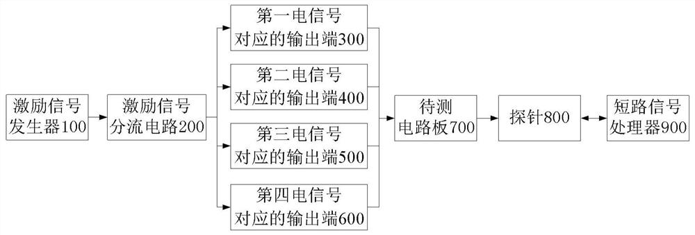
[0084] The present disclosure provides a finished printed circuit board short-circuit fault point tracking device, such as figure 1 As shown, it includes: an excitation signal generator 100 , an excitation signal shunt circuit 200 , four output terminals...


PUM


Abstract

The invention provides a finished printed circuit board short circuit fault point tracking device, which comprises an excitation signal generator, an excitation signal shunt circuit, four output ends, a probe and a short circuit signal processor, wherein the excitation signal generator sends out two paths of time-sharing independent output DC pulsating excitation signals, the two paths of excitation signals are divided into four paths of electric signals through an excitation signal dividing circuit, the four paths of electric signals are inputted into a circuit board to be tested through four output ends, one end of the probe makes relative contact with the circuit board to be tested to move, and collected short-circuit signals are transmitted to a short-circuit signal processor; and the short-circuit signal processor converts the short-circuit signal into an optical signal for indicating the position of a short-circuit fault point. The device can accurately search welding short-circuit points of tiny devices or damaged onboard devices and the like, is high in detection precision, has no damage to finished printed circuit boards and onboard components, and is advantaged in that the number of times of searching fault points of the circuit boards is small, the searching time is short and the like.

Description

technical field [0001] The present disclosure relates to the field of quality detection of finished printed circuit boards, in particular to a detection device and method for detecting short-circuit fault points of finished printed circuit boards. Background technique [0002] With the continuous development of electronic technology and computers, in recent years, the market demand for electronic terminal products including smart phones and notebook computers has been increasing, and the finished printed circuit board (Prineted Circuit Board Assembly, abbreviated as PCBA) as an electronic As the key components of end products, users have higher and higher quality requirements for them. [0003] In the process of producing finished printed circuit boards in the factory, the fault short circuit of electronic components, solder short circuit or assembly short circuit is an important factor that seriously affects the yield of finished printed circuit boards. Therefore, a finishe...

Claims


Application Information

Patent Timeline
Patent Type & Authority Applications(China)
IPC IPC(8): G01R31/28
CPCG01R31/2812
Inventor 陈星燎刘培瑞刘春平
Owner TIANJIN SINO GERMAN VOCATIONAL TECHNICAL COLLEGE
Learn More