
Snow accumulation prevention device suitable for electric power transmission rack

A technology for power transmission and snow prevention, which is applied in cable installation, overhead installation, electrical components, etc., can solve problems such as power waste, increased weight of power transmission racks, and cable twisting, and achieves improved processing efficiency and good snow removal effect. , to achieve the effect of automation

Inactive Publication Date: 2021-06-11
穆林(广州)数码科技有限公司
View PDF0 Cites 1 Cited by
  • Summary
  • Abstract
  • Description
  • Claims
  • Application Information

AI Technical Summary

Problems solved by technology

[0002] Electric power transmission refers to a way that a power plant or power supply is transmitted from one place to another. Power transmission generally uses cables and power transmission racks to transmit electric energy. Accumulation on the conveyor frame will increase the weight of the cable and the power conveyor frame, which may cause the distortion of the cable or the collapse of the power frame. However, the snow removal device at this stage cannot perform targeted snow removal at high altitudes. The snow removal device in the first stage will start to work when it snows, and the snow has not yet accumulated at this time, thus causing a waste of electric energy. In view of the above shortcomings, the present invention improves

Method used


Image

  • Snow accumulation prevention device suitable for electric power transmission rack
  • Snow accumulation prevention device suitable for electric power transmission rack
  • Snow accumulation prevention device suitable for electric power transmission rack

Examples


Embodiment Construction

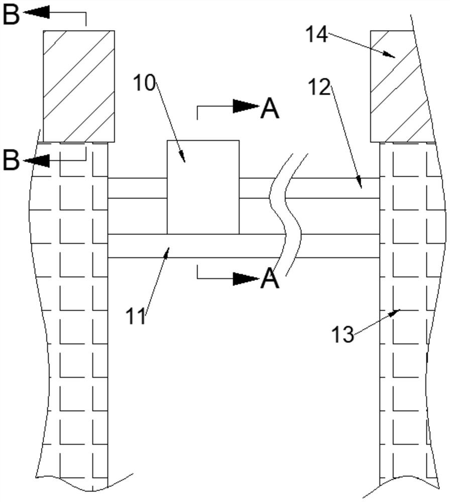
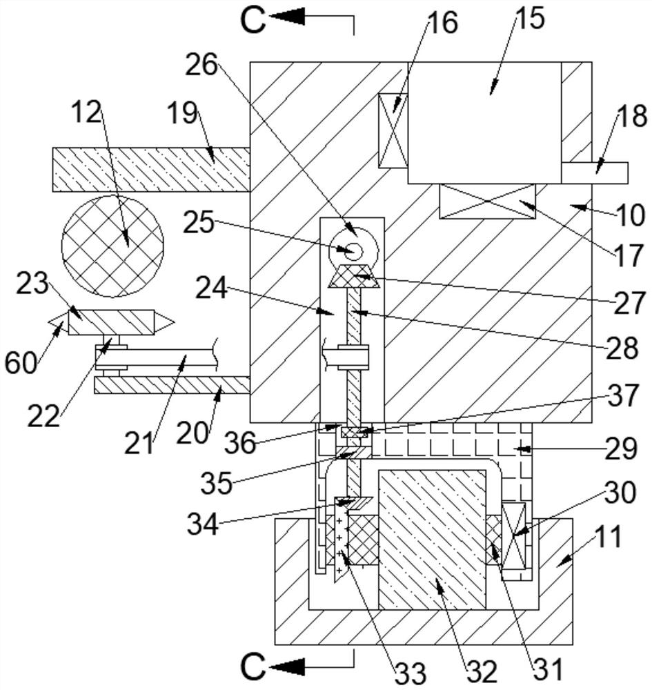
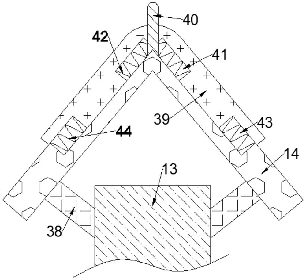
[0017] Combine below Figure 1-4 The present invention is described in detail, wherein, for the convenience of description, the orientations mentioned below are defined as follows: figure 1 The up, down, left, right, front and back directions of the projection relationship itself are the same.

[0018] combined with Figure 1-4 The snow prevention device applicable to the power transmission frame includes a snow clearing box 10 and a moving track 11 arranged under the snow clearing box 10, and a concave fixed block is fixed under the snow clearing box 10 29, the front side of the concave fixed block 29 is fixed with a power motor 30, the power motor 30 is rotated with a power shaft 31, and the power shaft 31 is fixed with a rolling tire 32, and the rolling tire 32 can The moving track 11 moves left and right, the rear side of the rolling tire 32 is fixed with a power bevel gear 33, and the concave fixed block 29 is provided with a penetration cavity 36, and the penetration c...


PUM


Abstract

The invention discloses a snow accumulation prevention device suitable for an electric power transmission rack. The snow accumulation prevention device comprises a snow cleaning box and a movement track arranged below the snow cleaning box, wherein a concave fixing block is fixedly arranged below the snow cleaning box. The snow accumulation prevention device is erected between two adjacent electric power transmission racks, so that the movable snow removal effect of a snow removal device can be achieved; the snow accumulation prevention device can operate when snow is accumulated to a certain degree, so that the phenomenon that electric energy is wasted due to the fact that snow removal work is started when snow snows is prevented; the snow accumulation prevention device has targeted snow removal measures for cables, the snow removal effect is better; the snow accumulation prevention device can remove snow on a track where a snow removal device moves, and the snow removal device is prevented from being unable to operate due to accumulation of snow on the track; a snow accumulation prevention mechanism is erected on a conveying frame, the collapse phenomenon of the conveying frame caused by snow accumulation is prevented; and meanwhile, automation of the treatment process is achieved, the treatment efficiency is greatly improved, and labor force is saved.

Description

technical field [0001] The invention relates to a snow prevention device suitable for a power transmission frame, and mainly relates to the technical field of power transmission. Background technique [0002] Electric power transmission refers to a way that a power plant or power supply is transmitted from one place to another. Power transmission generally uses cables and power transmission racks to transmit electric energy. Accumulation on the conveyor frame will increase the weight of the cable and the power conveyor frame, which may cause the distortion of the cable or the collapse of the power frame. However, the snow removal device at this stage cannot perform targeted snow removal at high altitudes. The snow removal device in the first stage will start to work when it snows, and the snow has not yet accumulated at this time, thereby causing a waste of electric energy. Aiming at the above-mentioned shortcomings, the present invention improves. Contents of the inventio...

Claims


Application Information

Patent Timeline
Patent Type & Authority Applications(China)
IPC IPC(8): H02G7/16
CPCH02G7/16
Inventor 詹德美
Owner 穆林(广州)数码科技有限公司
Learn More