
A high-gain converter applicable to photovoltaic charging and its control method

A control method and converter technology, which are applied in photovoltaic power generation, current collectors, and electrical variable regulation, etc., can solve the problems of large input inductor current stress, large input current pulsation rate, and insufficient boost capability, and achieve high voltage gain, The effect of continuous output current and simple structure

Active Publication Date: 2022-03-11
NANTONG UNIVERSITY
View PDF2 Cites 0 Cited by
  • Summary
  • Abstract
  • Description
  • Claims
  • Application Information

AI Technical Summary

Problems solved by technology

However, this structure has the following problems: (1) Under the condition of low input voltage, the current stress of the input inductor is relatively large, and a large inductance is required to ensure continuous current; (2) The input current pulse rate is large, the inductor current is large, and the loss is serious
It can effectively reduce the input current pulsation rate and reduce the average current stress of the switch tube, but there are disadvantages such as a large number of devices, complex structure, insufficient boosting capability, and high voltage stress.

Method used


Image

  • A high-gain converter applicable to photovoltaic charging and its control method
  • A high-gain converter applicable to photovoltaic charging and its control method
  • A high-gain converter applicable to photovoltaic charging and its control method

Examples


Embodiment Construction

[0029] The following will clearly and completely describe the technical solutions in the embodiments of the present application with reference to the accompanying drawings in the embodiments of the present application. Obviously, the described embodiments are only part of the embodiments of the present application, not all of them. Based on the embodiments in this application, all other embodiments obtained by persons of ordinary skill in the art without making creative efforts fall within the protection scope of the present invention.

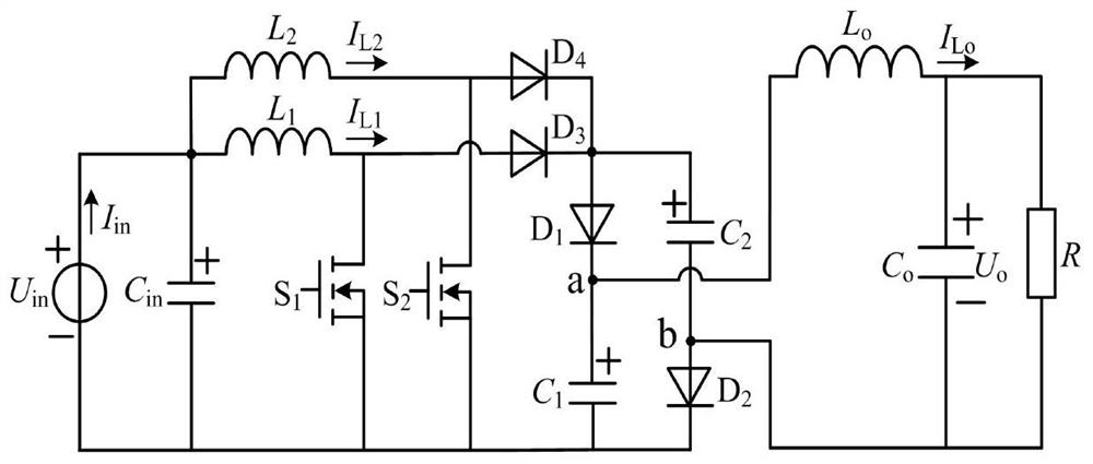
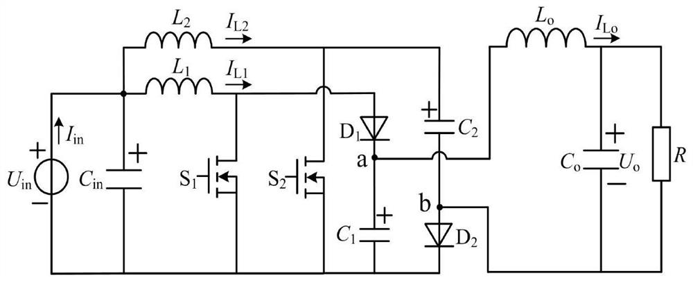
[0030] figure 2 A schematic circuit structure diagram of a high-gain converter that can be used for photovoltaic charging according to an embodiment of the present application is shown. As an exemplary and non-limiting embodiment, the converter includes an input power source U in , Input filter capacitor C in , the first inductance L 1 , the second inductance L 2 , the first switch tube S 1 , the second switch tube S 2 , the first diode...


PUM

PropertyMeasurementUnit
capacitanceaaaaaaaaaa

Abstract

The invention belongs to the technical field of DC-DC step-up conversion, and specifically relates to a high-gain converter and a control method thereof. in The positive pole of the input power supply is connected to the source pole of the first switching tube, the source pole of the second switching tube, the negative pole of the first capacitor, the cathode of the second diode, and the input filter capacitor C in The drain of the first switching tube is connected to the other end of the first inductor and the anode of the first diode; the drain of the second switching tube is connected to the other end of the second inductor and the positive electrode of the second capacitor; The cathode of the first diode is connected to the positive pole of the first capacitor and one end of the output filter inductor; the negative pole of the second capacitor is connected to the anode of the second diode, the negative pole of the output filter capacitor, and one end of the DC load; the output filter inductor The other end of is connected to the positive pole of the output filter capacitor and the other end of the DC load. The invention has the advantages of continuous input and output current, high voltage gain and the like.

Description

technical field [0001] The invention belongs to DC-DC step-up conversion technology, and in particular relates to a high-gain converter which can be used for photovoltaic charging and a control method thereof. Background technique [0002] Using the rooftop distributed photovoltaic power generation system to slowly charge electric vehicles can basically meet the electric energy needs of commuting and commuting in urban areas, and is conducive to the real realization of "zero-emission" green transportation. Since the terminal voltage of photovoltaic cells is usually much lower than that of electric vehicle power batteries, the photovoltaic slow charging system needs to use a higher-gain DC converter as the main circuit topology. In addition, the terminal voltage ripple of photovoltaic cells will affect the accuracy of MPPT control, which will seriously reduce the efficiency of MPPT. Therefore, capacitors are usually connected in parallel on the output side to filter the input...

Claims


Application Information

Patent Timeline
Patent Type & Authority Patents(China)
IPC IPC(8): H02M3/158H02J7/35
CPCH02M3/158H02J7/35Y02E10/56
Inventor 秦岭钱天泓许兴田民王亚芳周磊段冰莹
Owner NANTONG UNIVERSITY
Learn More