Supercharge Your Innovation With Domain-Expert AI Agents!

Spraying auxiliary cooling structure in vibration equipment

A technology for auxiliary cooling and vibration equipment, applied in the construction of electrical equipment components, vibration testing, cooling/ventilation/heating transformation, etc., can solve the problems of reducing heat dissipation air gaps, failure of moving parts, and increase of surface temperature, etc., to achieve strengthening The ability of convective heat transfer, the realization of transfer and balance, and the effect of simple structure

Pending Publication Date: 2021-06-11
6 DOF VIBRATION TESTING DEVICE WITH ELECTRODYNAMIC EXCITATION +1
View PDF0 Cites 0 Cited by
  • Summary
  • Abstract
  • Description
  • Claims
  • Application Information

AI Technical Summary

Problems solved by technology

Direct or inductively coupled vibration equipment generally adopts the method of fan exhaust to quickly reduce the surface temperature, so as to realize the thermal balance of the surface of the driving coil or induction ring, but in the test environment of high value, strong vibration and long time, the driving coil Or the large induction current of the induction ring part causes its surface to continue to have a high temperature, causing its radial dimension to expand and increase, the original movement air gap channel is damaged, and the air gap size is correspondingly reduced, thereby reducing the cooling efficiency of the fan exhaust , it is easy to cause the failure of the moving parts, which affects the normal use of the vibration equipment. At the same time, after the induction ring on the moving parts passes through the induction current, heat is generated and accumulated rapidly, causing the surface temperature to increase, causing the induction ring to expand radially, thereby reducing the original Some heat dissipation air gaps affect the heat dissipation efficiency of the induction ring. Only the conventional air cooling heat dissipation method cannot satisfy its long-term stable working state.

Method used


Image

  • Spraying auxiliary cooling structure in vibration equipment
  • Spraying auxiliary cooling structure in vibration equipment
  • Spraying auxiliary cooling structure in vibration equipment

Examples


Embodiment Construction

[0020] The following will clearly and completely describe the technical solutions in the embodiments of the present invention with reference to the accompanying drawings in the embodiments of the present invention. Obviously, the described embodiments are only some, not all, embodiments of the present invention. Based on the embodiments of the present invention, all other embodiments obtained by persons of ordinary skill in the art without making creative efforts belong to the protection scope of the present invention.

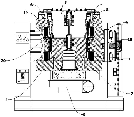
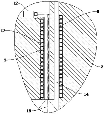
[0021] see Figure 1~3 , in the embodiment of the present invention, the internal spray cooling structure of the vibrating equipment includes a lower plate 1 and an upper plate 4, a suction hood 3 is arranged in the middle below the lower plate 1, and a The central magnetic pole 2, the lower pole plate 1 is located above the central magnetic pole 2, and the lower excitation 7 is arranged on the periphery of the central magnetic pole 2, the upper excitation 6 i...


PUM


Abstract

The invention discloses a spraying auxiliary cooling structure in vibration equipment. The spraying auxiliary cooling structure comprises a lower pole plate and an upper pole plate, wherein an air suction cover is arranged in the middle below the lower pole plate, a central magnetic pole is fixedly connected to the middle above the lower pole plate, a lower excitation is arranged on the periphery of the central magnetic pole above the lower pole plate, an upper excitation is arranged on the periphery above the central magnetic pole, and the upper pole plate is arranged on one side above the upper excitation. According to the invention, the spraying auxiliary cooling structure is simple in structure and easy to install and maintain, the cooling effect is obviously better than that of pure fan cooling, heat conduction and gasification modes are adopted, the convective heat exchange capacity is enhanced, rapid transfer and balance of the temperature difference in the vibration table body are achieved, and the spraying auxiliary cooling structure can be applied to cooling of the induction ring part of the induction type vibration table, is particularly suitable for heat dissipation of an induction ring in a high-thrust induction type vibration table, and can achieve the function of rapidly cooling a moving coil part of common electric vibration equipment.

Description

technical field [0001] The invention relates to the field of vibration equipment cooling, in particular to a structure for assisting cooling and cooling by spraying inside the vibration equipment. Background technique [0002] The electric vibration table is the key test equipment necessary for the development of aerospace (military) products such as rockets, missiles, and satellites. It is widely used in product strength checks, transportation environment testing, and reliability tests. The development of products in various industries such as trains and the verification of products under simulated working conditions. The vibration test equipment drives the moving parts through the interaction of the alternating current of the driving coil and the constant magnetic field to generate the exciting force. [0003] In medium and small direct-coupled vibration equipment, the moving parts are rigidly formed by the moving coil skeleton and the driving coil through high temperatur...

Claims


Application Information

Patent Timeline
IPC IPC(8): H05K7/20G01M7/02
CPCG01M7/02H05K7/20145H05K7/20309
Inventor 秦亚明张奎华陈良勇张红彩卫国陈晨
Owner 6 DOF VIBRATION TESTING DEVICE WITH ELECTRODYNAMIC EXCITATION
Features
  • R&D
  • Intellectual Property
  • Life Sciences
  • Materials
  • Tech Scout
  • Unparalleled Data Quality
  • Higher Quality Content
  • 60% Fewer Hallucinations
Learn More