Metal bar clamping type double-section shearing blanking device and blanking method

A clamping, metal rod technology, applied in the direction of shearing devices, metal processing equipment, shearing machine equipment, etc., can solve the problems of reducing the utilization rate of raw materials, and achieve the goal of improving the efficiency of blanking work, uniform force, and avoiding tilting Effect

Active Publication Date: 2021-06-15
XIAN UNIV OF SCI & TECH
View PDF8 Cites 1 Cited by
  • Summary
  • Abstract
  • Description
  • Claims
  • Application Information

AI Technical Summary

Problems solved by technology

The shear speed directly affects the cutting quality of the blank section. Increasing the shear speed can improve the section quality of the material to a certain extent. However, obtaining the best shear speed for a specific material often requires additional material and manpower, which reduces the utilization rate of raw materials.

Method used


Image

  • Metal bar clamping type double-section shearing blanking device and blanking method
  • Metal bar clamping type double-section shearing blanking device and blanking method
  • Metal bar clamping type double-section shearing blanking device and blanking method

Examples


Embodiment 1

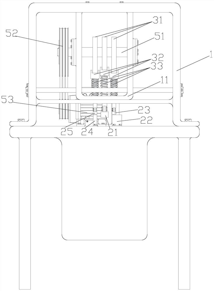
[0055] Such as Figure 1-9 As shown, this embodiment provides a metal rod clamping type double-stage shearing blanking device, including a housing, and the housing 1 is provided with a pressing blanking unit and a cam mechanism;

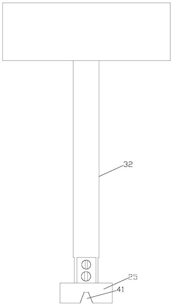
[0056] The pressing and blanking unit includes a cutter, a first pad 22, a first pressure block 23, a second pad 24 and a second pressure block 25, and the first pad 22 is arranged opposite to the first pressure block 23 Below and the first spacer 22 is fixed in the housing 1, the second spacer 24 is arranged directly below the second pressing block 25 and the second spacer 24 is fixed in the housing 1;

[0057] The cam mechanism includes a first cam assembly for driving the first pressing block 23 close to or away from the first cushion block 22, a second cam assembly for driving the tool to move, and a second cam assembly for driving the second pressing block 25 close to or away from the first cushion block 22. a third cam assembly away from the s...

Embodiment 2

[0075] This embodiment provides a method for shearing and blanking using the metal rod clamping type double-stage shearing and blanking device of Example 1, including the following steps:

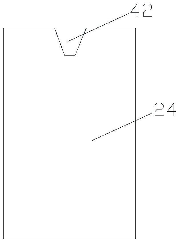
[0076] Step 1. Select a metal bar stock with a material of 304 stainless steel, a length of 40 mm, and a diameter of 10 mm. A V-shaped incision 43 is pre-cut on the bar stock. The incision 43 includes a metal bar located inside the bar stock. The rounded tip and the opening extending from the rounded tip to the bar surface, the fillet radius of the rounded tip is 0.2mm, the depth of the cutout 43 is 1.5mm, the number of cutouts 43 There are four, the four cutouts 43 are divided into two groups, the cutouts 43 of the two groups are arranged at intervals, the central axis line of the two cutouts 43 in the same group coincides and the central axis line is perpendicular to the rod The long axis of the material is obtained to obtain the bar material 4 to be sheared;

[0077] Step 2, adjust and ...


PUM


Abstract

The invention discloses a metal rod clamping type double-section shearing blanking device and a blanking method. The device comprises a shell, a pressing discharging unit and a cam mechanism. The pressing discharging unit comprises a cutter, a first cushion block, a first pressing block, a second cushion block and a second pressing block. The cam mechanism comprises a first cam assembly, a second cam assembly and a third cam assembly; and the first cam assembly, the second cam assembly and the third cam assembly each comprise a cam, a compression state spring and a driven rod. The first pressing block is fixed to the driven rod of the first cam assembly. The cutter is fixed on the driven rod of the second cam assembly. The second pressing block is fixed to the driven rod of the third cam assembly. The cutter comprises a cutter body and two cutter edges; and a through hole is formed in the cutter body. According to the metal rod clamping type double-section shearing blanking device, clamping type double-section shearing blanking of the metal bars can be achieved, the bars are directly blanked after being sheared, and the blanking working efficiency is improved.

Description

technical field [0001] The invention belongs to the technical field of mechanical processing, and in particular relates to a metal rod clamping type double-stage shearing blanking device and a blanking method. Background technique [0002] The precision blanking of metal bars is an important direction of the machining industry, and it is the trend of green and environmentally friendly manufacturing. [0003] At present, there are three commonly used blanking methods: cutting blanking, shearing blanking, and sawing blanking. However, in the process of using the above traditional method for bar blanking, there may be inclination, slump, ellipticity and unevenness, etc., resulting in the defects that the machining accuracy of the material cannot meet the accuracy requirements required by the current mechanical processing manufacturing industry. Fracture toughness It is one of the key factors affecting the cutting accuracy. The properties of the material itself and the process...

Claims


Application Information

Patent Timeline
Patent Type & Authority Applications(China)
IPC IPC(8): B23D31/00
CPCB23D31/002
Inventor 钟斌强轩轩张成财
Owner XIAN UNIV OF SCI & TECH
Why Eureka
Try Eureka