
Grouting device for coal mine water disaster prevention and control

A technology for water hazards and coal mines, applied in safety devices, drainage, mining equipment, etc., it can solve the problems of insufficient pouring strength, damage to the grouting pipe body, and increased use costs, and achieve the effect of uniform mixing and large kinetic energy.

Pending Publication Date: 2021-06-15
魏贺
View PDF1 Cites 2 Cited by
  • Summary
  • Abstract
  • Description
  • Claims
  • Application Information

AI Technical Summary

Problems solved by technology

[0005] 1. In the above patent, when the grouting pipe is blocked from entering the prefabricated hole, the grouting pipe is penetrated by rotating and pressing the grouting pipe. This will not only cause serious damage to the grouting pipe body, but also increase the cost of use, and the penetration effect will also be reduced. It is not ideal. When encountering hard rock and soil, it still cannot continue to descend smoothly
[0006] 2. In the above patents, the outflow of the grouting liquid is controlled by a one-way solenoid valve. Although this can prevent the backflow of the grouting liquid, the perfusion effect of the grouting liquid is not ideal. In the rock and soil around the barrel, and the grouting force is insufficient, resulting in poor penetration of the grouting fluid in the rock and soil

Method used


Image

  • Grouting device for coal mine water disaster prevention and control
  • Grouting device for coal mine water disaster prevention and control
  • Grouting device for coal mine water disaster prevention and control

Examples


Embodiment Construction

[0038] The following will clearly and completely describe the technical solutions in the embodiments of the present invention with reference to the accompanying drawings in the embodiments of the present invention. Obviously, the described embodiments are only some, not all, embodiments of the present invention. Based on the embodiments of the present invention, all other embodiments obtained by persons of ordinary skill in the art without making creative efforts belong to the protection scope of the present invention.

[0039]In the description of the present invention, it should be noted that the orientation or positional relationship indicated by the terms "vertical", "upper", "lower", "horizontal" etc. is based on the orientation or positional relationship shown in the drawings, and is only In order to facilitate the description of the present invention and simplify the description, it does not indicate or imply that the device or element referred to must have a specific or...


PUM


Abstract

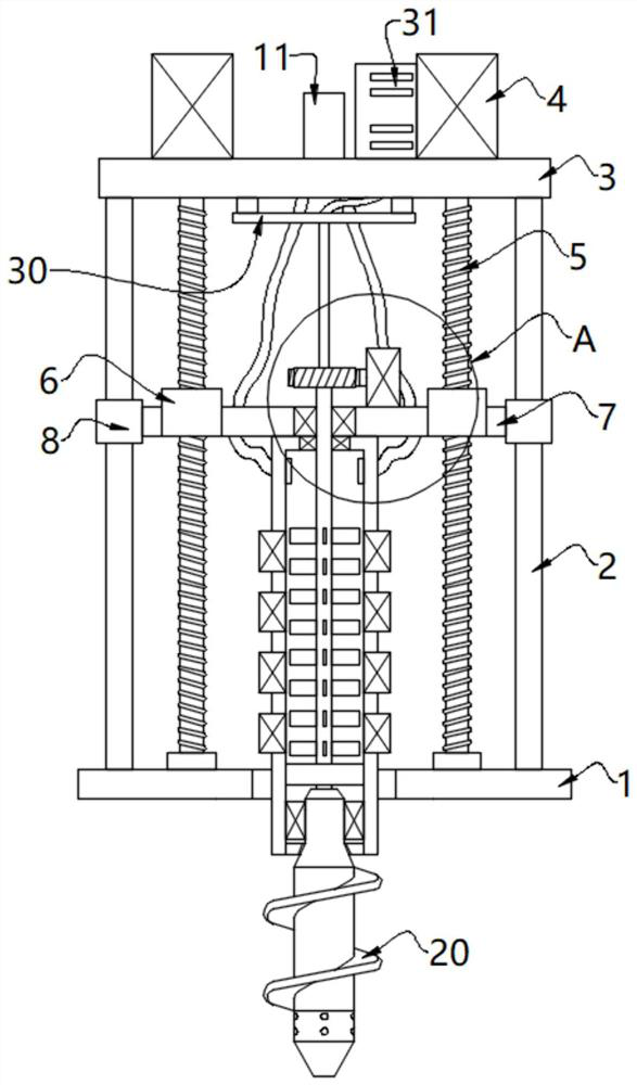
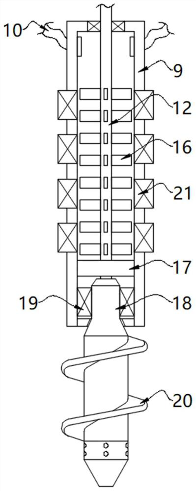
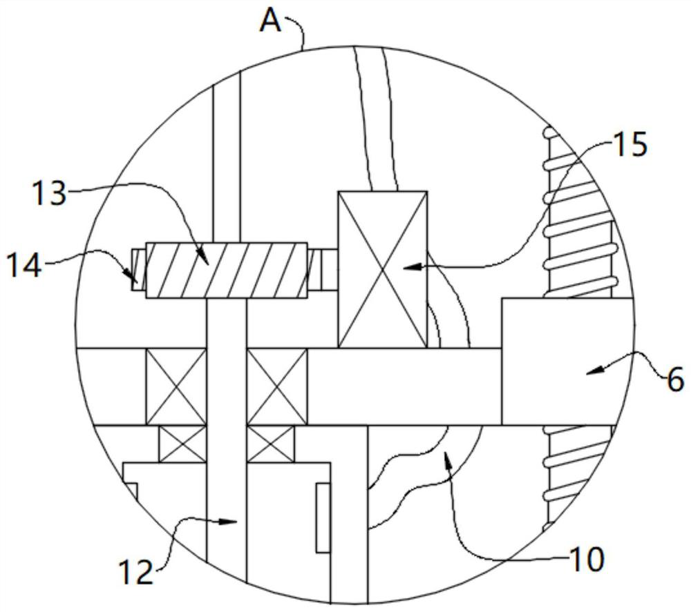
The invention relates to the technical field of coal mine water disaster prevention and control, and discloses a grouting device for coal mine water disaster prevention and control. The grouting device for coal mine water disaster prevention and control comprises a bottom plate, wherein supporting columns are fixedly mounted on two sides of the top of the bottom plate, a top plate is fixedly mounted on the tops of the supporting columns, and a lifting motor is fixedly mounted on the top of the top plate; a screw rod is fixedly mounted at the top of an output shaft of the lifting motor, a nut is in threaded connection with the outer wall of the screw rod and fixedly mounted in a lifting plate, and the lifting motor operates to drive the lifting plate and a grouting cylinder to descend through transmission of the screw rod and the nut, so that the grouting cylinder penetrates into a ground hole; a driving motor runs to drive a rotating shaft, a connecting column and a soil loosening auger to rotate through transmission of a worm gear and a worm, the soil loosening auger rotates to loosen a rock-soil body below the grouting cylinder, sinking of the grouting cylinder is facilitated, and the grouting cylinder cannot be blocked by the hard rock-soil body. The grouting device for coal mine water disaster prevention and control has the advantages of being convenient to drill into ground pores, uniform in grouting and large in grouting force.

Description

technical field [0001] The invention relates to the technical field of coal mine water disaster prevention and control, in particular to a grouting device for coal mine water disaster prevention and control. Background technique [0002] Coal mine floods affect the progress and quality of mine construction, worsen the working environment of workers, increase the drainage facilities and drainage costs of mines, and bring unsafe factors to coal mine production. In severe cases, well flooding accidents even occur, causing major loss of life and property. loss. In the process of coal mining, it is very easy to communicate with old kiln water accumulation, water leakage accidents in car-making mines, and coal mine water damage accidents will also lead to erosion and weakening of surrounding rocks and induce secondary disasters. The hydrogeological conditions of my country's coalfields are complex, and currently about 80% of the coal reserves to be mined are threatened by relativ...

Claims


Application Information

Patent Timeline
IPC IPC(8): E21F16/00E21D11/10E21B33/138
CPCE21B33/138E21D11/10E21F16/00
Inventor 魏贺陈超
Owner 魏贺
Learn More